Pressure regulating valve for common rail fuel injection systems

Inactive Publication Date: 2005-02-03
ROBERT BOSCH GMBH
View PDF8 Cites 11 Cited by
  • Summary
  • Abstract
  • Description
  • Claims
  • Application Information

AI Technical Summary

Benefits of technology

[0009] The object of the invention is to improve the pressure regulating valve known from the prior art in such a way that even if the electromagnetic closing force fails, it generates a minimum pressure at the valve outlet and thus makes emergency vehicle operation possible.

Problems solved by technology

However, if the electromagnet should fail because of a malfunction, at least emergency vehicle operation is still possible.

Method used


Image

  • Pressure regulating valve for common rail fuel injection systems
  • Pressure regulating valve for common rail fuel injection systems

Examples


Embodiment Construction

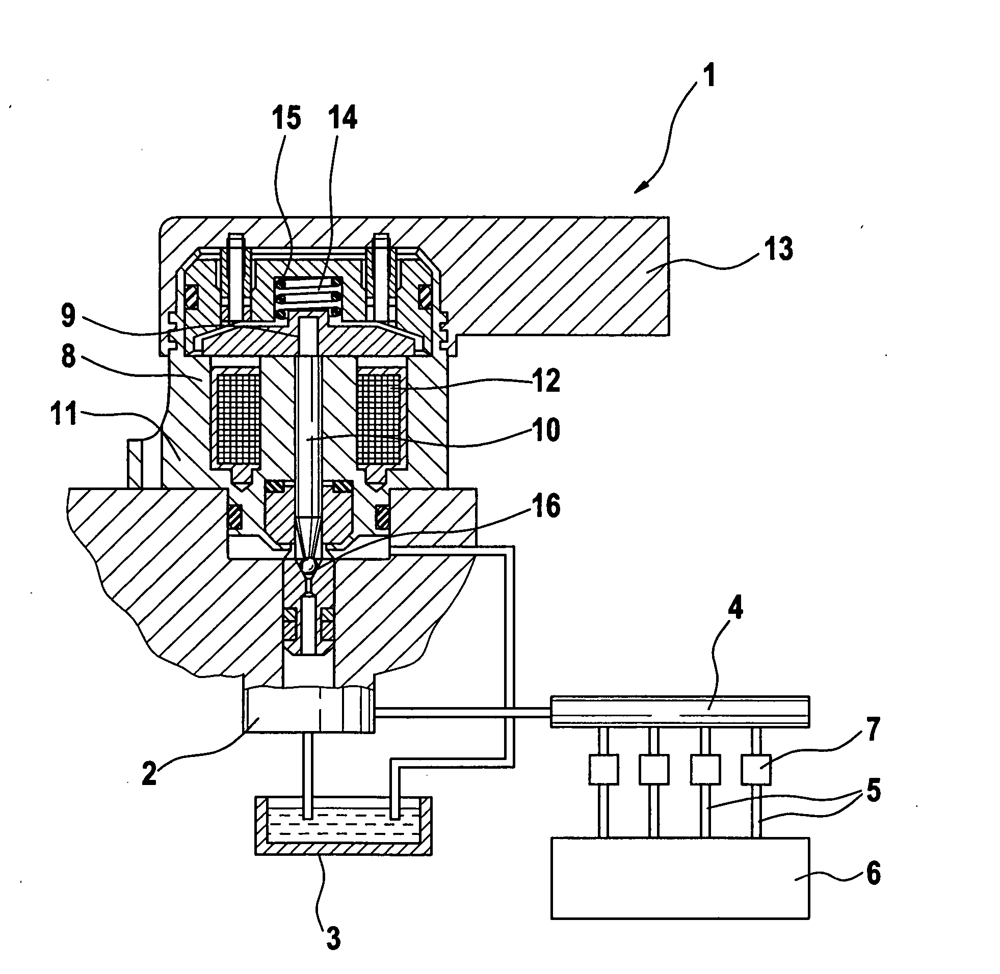
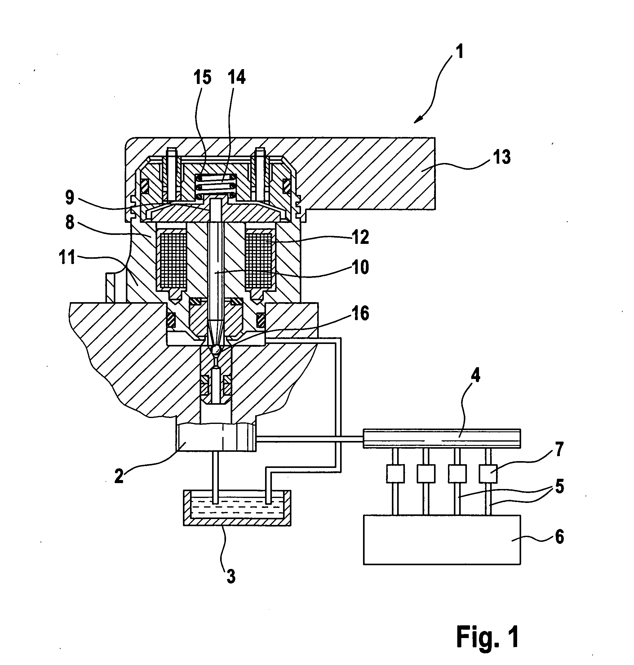
[0014] In FIG. 1, a longitudinal section through a pressure regulating valve 1 is shown. Additionally, a common rail fuel injection system for internal combustion engines, in particular self-igniting engines, is shown in schematic form. The common rail fuel injection system has a high-pressure pump 2, by which fuel at high pressure is pumped out of a fuel tank 3 into a common rail 4. The common rail 4 is embodied in tubular form as a so-called rail. From the common rail 4, lines 5 lead to the injection locations of an engine 6, in each of which a valve 7 is disposed; for adjusting the pressure in the common rail 4, the pressure regulating valve is provided, which may be disposed at the outlet of the high-pressure pump 2 or at the common rail 4.

[0015] The pressure regulating valve 1 itself has a valve body 8 with a bore 9 in which a pistonlike valve member 10 is disposed axially displaceably. A fastening flange 11 is disposed on the valve body 8, and by way of this flange the valve ...


PUM


Abstract

A pressure regulating valve for regulating the pressure in a common rail, having a pistonlike valve member guided axially displaceably in a bore, which valve member acts in the closing direction on a closing element and presses it against a valve seat, and the valve member forms an armature of an electromagnet that can be supplied with electric current. The valve is additionally equipped with a mechanical spring, which likewise presses the valve member in the direction of the valve seat, and whose spring constant is designed such that the valve cannot be opened until beyond a predetermined minimum fuel pressure of greater than or equal to 250 bar. In this way, even in the event that the electromagnetic closing force should fail, a minimum pressure at the valve outlet is generated and thus an injection event is made possible.

Description

BACKGROUND OF THE INVENTION [0001] 1. Field of the Invention [0002] The invention relates to a common rail fuel injection system for internal combustion engines, having a pressure regulating valve for regulating the pressure in a common rail, having a pistonlike valve member guided axially displaceably in a bore, which valve member acts in the closing direction on a closing element and presses it against a valve seat, and the valve member forms an armature of an electromagnet that can be supplied with electric current. [0003] 2. Description of the Prior Art [0004] Many versions of pressure regulating valves of the type with this invention is concerned are known for regulating the pressure in a common rail. The pressure regulating valve has a pistonlike valve member, which is guided axially displaceably in a bore and can move counter to a force which is exerted on the valve member preferably by the current in an electromagnet. The force acts in the closing direction, so that the valv...

Claims


Application Information

Patent Timeline
Patent Type & Authority Applications(United States)
IPC IPC(8): F02M37/00F02M55/00F02M55/02F02M59/46F02M63/00F02M63/02
CPCF02M55/00F02M63/0003F02M63/0015F02M63/025F02M63/0043F02M63/0225F02M63/004F02M63/0052
Inventor BRAEUER, CHRISTIANHOLL, STEFAN
Owner ROBERT BOSCH GMBH
Why Eureka
Try Eureka