Lens aid and lens aid system and techniques for the insertion and removal of contact and scleral lenses

a technology of lens cup and lens cup, which is applied in the field of lens cup, can solve the problems of adversely affecting the vision of the wearer, insufficient improvement of vision, irritation and complications, etc., and achieve the effects of reducing the chances of suction, safe hands-free insertion, and easy removal from the lens cup

Inactive Publication Date: 2018-03-13
HOPPER THOMAS P
View PDF19 Cites 5 Cited by
  • Summary
  • Abstract
  • Description
  • Claims
  • Application Information

AI Technical Summary

Benefits of technology

[0012]It is a feature and advantage of the present invention to provide a lens aid system having a support stand that may standalone without requiring a user to hold the support stand, the support stand holding preferably a scleral lens or contact lens within a lens cup to allow for a safe hands-free insertion technique of the lens by looking down on the top with a clear view down or surface on which on the LNSAID™ system is sitting, letting a person's neck muscles control the insertion of the lens into the eye, and freeing both hands to have one hand hold the upper eyelid open and the second hand to hold the lower eyelid open. Because a scleral lens has a larger diameter than a typical soft lens, using both hands may significantly aid in the insertion of the lens particularly where even if a few eyelashes being captured under the lens will result in failure of proper insertion.
[0013]In embodiments of the lens aid system a soft pliable lens cup applies minimal pressure against the eye, and importantly flexes at the immediate point of contact with the eye to correctly align the position of the lens within the eye as the eye is brought against the lens and is captured by the eyelids as they are released by the user's fingers.
[0014]In embodiments, the lens cup may have smooth continuous ripples or ridges that allow the lens to be removed from the lens cup more easily by allowing air to enter under the edge of the lens and between the ridges to reduce the chances of any suction between the lens and lens cup that may occur.
[0015]Embodiments of the lens cup are made of antibacterial material such as a medical grade polypropylene, a soft pliable plastic silicone, closed cell waterproof foam, or rubber like material with soft near forty (40) durometer qualities or be treated with an antibacterial coating.
[0016]Embodiments of the lens cup may be removable from the lens aid system for cleaning or replacement.
[0017]In embodiments, the lens cup may have crosshair lines along the curved surface of the cup to assist the user in determining the proper positioning and centering of their eye over the lens aid and support tube of the lens aid system for proper alignment of the lens for insertion.

Problems solved by technology

For some people the wearing of smaller conventional contact lenses that only cover a portion of the cornea of the eye may not adequately improve vision and may cause irritation and complications.
This is of concern because the incorrect insertion of these larger lenses may cause an air bubble or eyelash entrapment between the lens and eye which may irritate and adversely affect the wearer's vision.
For some, these procedures require a level of coordination that is very difficult to attain particularly because the eye has a normal aversion to having anything inserted and making contact with it.
Also, the spreading “V” shape is hard to learn so that you do not contaminate your own eyelids with your fingers.
One problem with this technique is that the cup supporting the scleral lens can move laterally disturbing the insertion, as you squeeze the base.
Also, each of these methods has the fundamental problem of requiring one hand to hold the lens steady and one hand to hold the eyelids open.
They all also interfere with a clear view to a mirror due to how the lens is being supported by the hand and fingers.
Also, any flinching of either the eyelids or fingertips can result in the lens being dropped, damaged and even lost.
The opaque material and large diameter base block a clear view to a mirror to see the axis of the lens and substantially prevents satisfactory mirror use to assist in the alignment of the lens to the eye.
The rounded upper portion of the plunger base stand also will send an accidently falling lens off in a lateral direction possibly off the table to the floor making it difficult to retrieve.
The added patience and dexterity required to insert a scleral lens using these procedures of the prior art, can be uncomfortable for a user and may deter a user from choosing a scleral lens regardless of the added benefits of improved vision and greater durability.

Method used


Image

  • Lens aid and lens aid system and techniques for the insertion and removal of contact and scleral lenses
  • Lens aid and lens aid system and techniques for the insertion and removal of contact and scleral lenses
  • Lens aid and lens aid system and techniques for the insertion and removal of contact and scleral lenses

Examples


Embodiment Construction

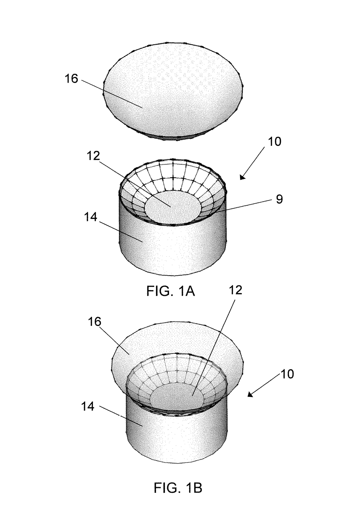
[0098]An embodiment of a lens cup 10 of the present invention is shown in FIG. 1A. Embodiments of the lens cup 10 have an upper surface 12 and a cylindrical body 14. The upper surface 12 is formed with parabolic curved walls and a center portion providing for a large diameter scleral or contact lens 16 to be placed and supported along the edge 9 of the upper surface 12 as shown in FIG. 1B. The lens cup 10 is made from antibacterial, antimicrobial material such as a medical grade polypropylene, a soft pliable plastic silicone, closed cell foam, or rubber like material with soft near forty (40) durometer qualities or another type of material that will compress and allow its form to be altered easily as the lens 16 sitting on top is brought against the eye. This edge flexibility feature is to allow and provide for the absolute correct precision and final alignment of the axis of the lens 16 at the immediate point where the lens 16 initially makes contact with the eye. The soft and plia...


PUM


Abstract

A lens aid, lens aid system and powered light source combined with a mirror that uses a lens cup of soft pliable material providing an improved visual method including a hands-free or one hand method for the insertion of a contact lens and more preferably a scleral lens into the eye.

Description

RELATED PATENT APPLICATION[0001]This application claims the benefit of U.S. Provisional Patent Application No. 62 / 318,458 filed Apr. 5, 2016 entitled LENS AID AND LENS AID SYSTEM AND TECHNIQUES FOR THE INSERTION AND REMOVAL OF CONTACT AND SCLERAL LENSES which is hereby incorporated herein by reference in the entirety.FIELD OF THE INVENTION[0002]The present invention is related to a lens aid for the particular insertion of a large scleral lens, and / or contact lens into the eye. The lens aid of the present invention is referred to herein as a LNSAID™ with LNSCUP™ lens aid system and this lens aid system also referred to as the LNSAID™ Kit.BACKGROUND OF THE INVENTION[0003]For some people the wearing of smaller conventional contact lenses that only cover a portion of the cornea of the eye may not adequately improve vision and may cause irritation and complications. Therefore, for some, a larger scleral lens that extends over the entire corneal surface and rests on a portion of the scler...

Claims


Application Information

Patent Timeline
Patent Type & Authority Patents(United States)
IPC IPC(8): A61F9/00
CPCA61F9/0061
Inventor HOPPER, THOMAS P.
Owner HOPPER THOMAS P
Why Eureka
Try Eureka