
Radio relay appliance activation

a radio relay and appliance technology, applied in the field of remote control of appliances, can solve the problems of complex electronic devices placed within the vehicle, operation together with existing remote controls, and difficulty experienced by users programming such devices to work with existing garage door opener receivers

Inactive Publication Date: 2005-02-03
LEAR CORP
View PDF97 Cites 73 Cited by
  • Summary
  • Abstract
  • Description
  • Claims
  • Application Information

AI Technical Summary

Benefits of technology

The present invention provides a system for controlling an appliance using radio frequency signals. The system includes a radio receiver that receives signals from existing radio frequency transmitters with specific characteristics. The system also includes a radio relay that learns the characteristics of the existing transmitters and a new transmitter with different characteristics. The radio relay then transmits signals to the receiver with the learned characteristics. The system can also determine the rolling code of the existing transmitter and use it to activate a new appliance. The invention allows for seamless control of appliances using different radio frequency signals.

Problems solved by technology

One problem with such devices is the need to put a complex electronic device within the vehicle, where space is a premium.
Another problem with such devices is the requirement that they operate together with existing remote controls.
Yet another problem is the difficulty experienced by users programming such devices to work with existing garage door opener receivers.
Such installation is beyond the capabilities of some users.

Method used


Image

  • Radio relay appliance activation
  • Radio relay appliance activation
  • Radio relay appliance activation

Examples


Embodiment Construction

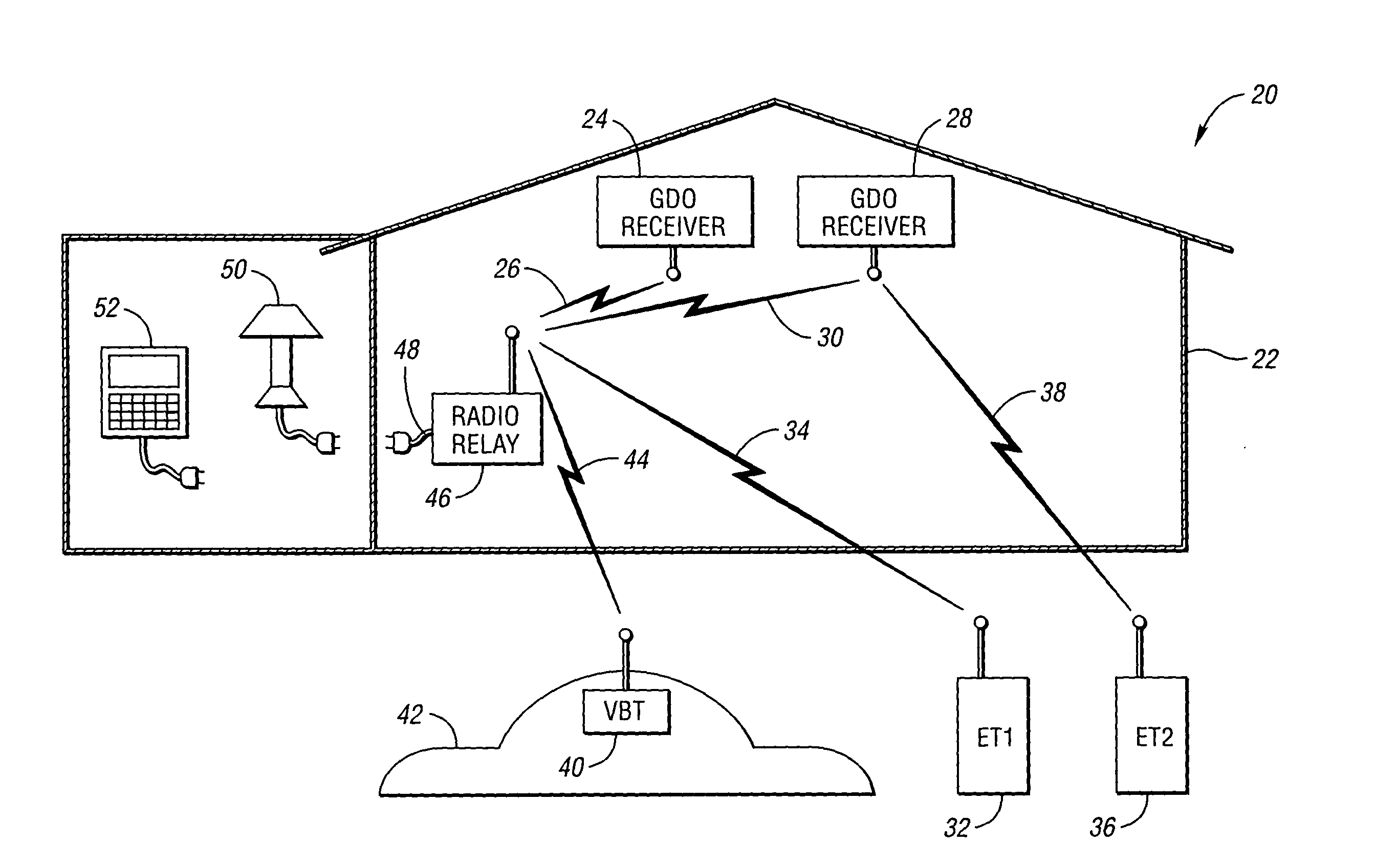
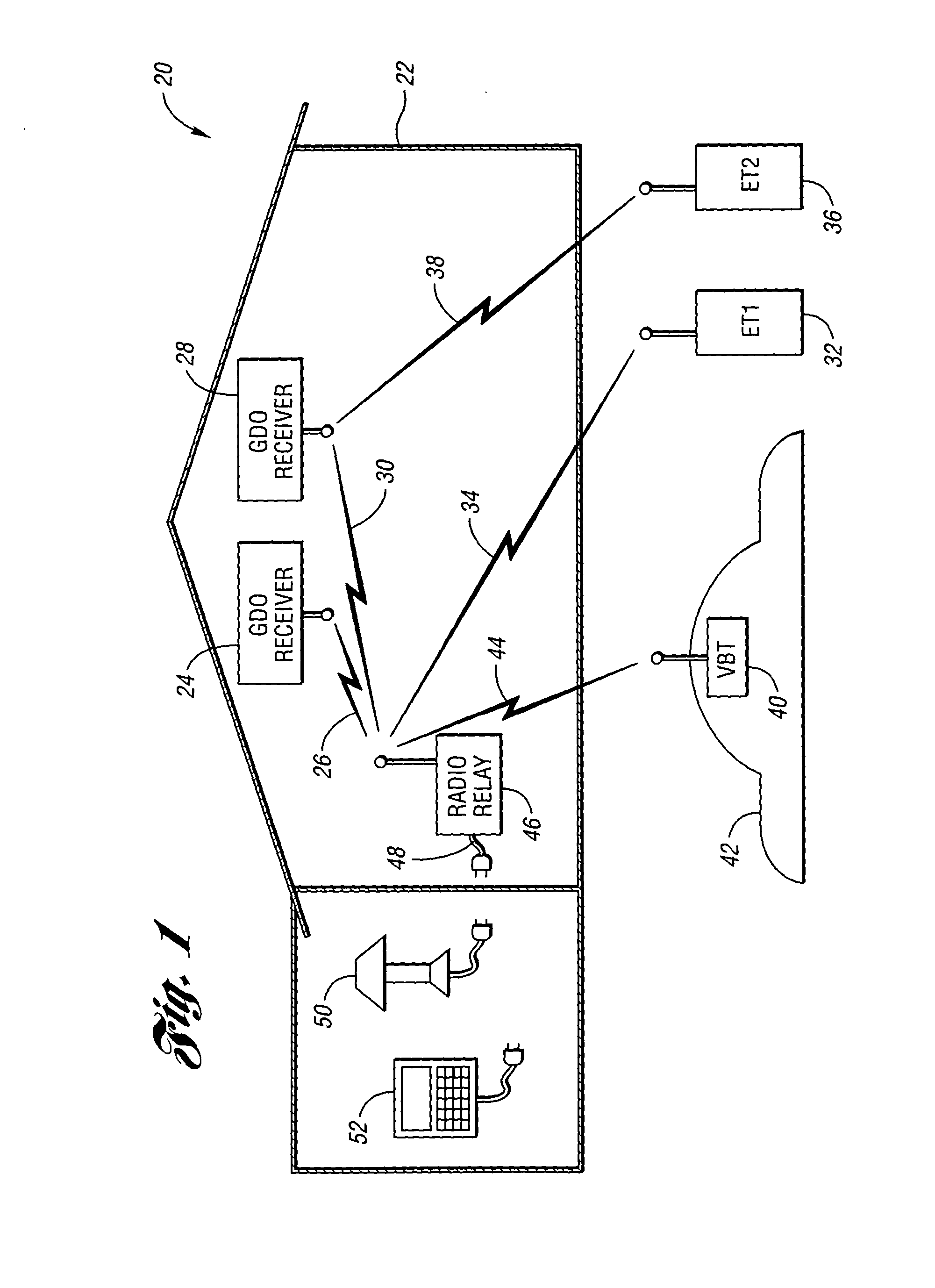
[0027] Referring to FIG. 1, a block diagram illustrating an appliance control system according to an embodiment of the present invention is shown. An appliance control system, shown generally by 20, allows one or more appliances to be remotely controlled using radio transmitters. In the example shown, radio frequency remote controls are used to operate garage door openers. However, the present invention may be applied to controlling a wide variety of appliances such as other mechanical barriers, lighting, alarm systems, temperature control systems, and the like.

[0028] Appliance control system 20 includes garage 22 having two garage doors, not shown. First garage door opener (GDO) receiver 24 receives radio frequency control signals 26 for controlling a first garage door opener. First received control signals 26 have predetermined receiver characteristics for operation with GDO receiver 24. Garage 22 also includes second GDO receiver 28 receiving radio frequency control signals 30 f...


PUM


Abstract

Remote appliance activation can be achieved by relaying between radio frequency transmission schemes having different characteristics. A radio receiver receives radio frequency control signals for controlling the appliance. Each existing radio frequency transmitter is specifically designed to transmit wireless radio frequency control signals having receiver characteristics to the radio receiver. A new wireless radio frequency transmitter has transmitter characteristics, at least one of which is different from receiver characteristics. A radio relay learns the receiver characteristics from one of the existing transmitters and learns at least one transmitter characteristic from the new transmitter. Then, when an appliance radio frequency activation command is received from the new transmitter, the radio relay transmits a new radio frequency appliance activation command having the learned receiver characteristics.

Description

BACKGROUND OF THE INVENTION [0001] 1. Field of the Invention [0002] The present invention relates to remote control of appliances such as, for example, garage door openers. [0003] 2. Background Art [0004] Home appliances, such as garage door openers, security gates, home alarms, lighting, and the like, may conveniently be operated from a remote control. Typically, the remote control is purchased together with the appliance. The remote control transmits a radio frequency activation signal which is recognized by a receiver associated with the appliance. Aftermarket remote controls are gaining in popularity as such devices can offer functionality different from the original equipment remote control. Such functionality includes decreased size, multiple appliance interoperability, increased performance, and the like. Aftermarket controllers are also purchased to replace lost or damaged controllers or to simply provide another remote control for accessing the appliance. An example applica...

Claims


Application Information

Patent Timeline
Patent Type & Authority Applications(United States)
IPC IPC(8): G08C17/02H04L12/28
CPCG08C17/02G08C2201/40G08C2201/62H04W88/04H04L12/2803H04L12/282G08C2201/92
Inventor CHUEY, MARK D.
Owner LEAR CORP
Learn More