Color filter, method of manufacturing such color filter, method of depositing liquid material to manufacture such color filter, display device having such color filter, method of manufacturing liquid crystal display device having such color filter, electro-optic device having such color filter, electronic instrument having such color filter, method of manufacturing such electronic instrument

Inactive Publication Date: 2005-02-03
SEIKO EPSON CORP
View PDF7 Cites 11 Cited by
  • Summary
  • Abstract
  • Description
  • Claims
  • Application Information

AI Technical Summary

Benefits of technology

[0009] Therefore, an object of the present invention is to provide a color filter that has good color balances in a reflective display mode and in a transmissive display mode. Such color filter is configured so that a liquid material can be appropriately coated thereon. Another object o

Problems solved by technology

Accordingly, the display is inevitably darkened because the

Method used


Image

  • Color filter, method of manufacturing such color filter, method of depositing liquid material to manufacture such color filter, display device having such color filter, method of manufacturing liquid crystal display device having such color filter, electro-optic device having such color filter, electronic instrument having such color filter, method of manufacturing such electronic instrument
  • Color filter, method of manufacturing such color filter, method of depositing liquid material to manufacture such color filter, display device having such color filter, method of manufacturing liquid crystal display device having such color filter, electro-optic device having such color filter, electronic instrument having such color filter, method of manufacturing such electronic instrument
  • Color filter, method of manufacturing such color filter, method of depositing liquid material to manufacture such color filter, display device having such color filter, method of manufacturing liquid crystal display device having such color filter, electro-optic device having such color filter, electronic instrument having such color filter, method of manufacturing such electronic instrument

Examples


first embodiment

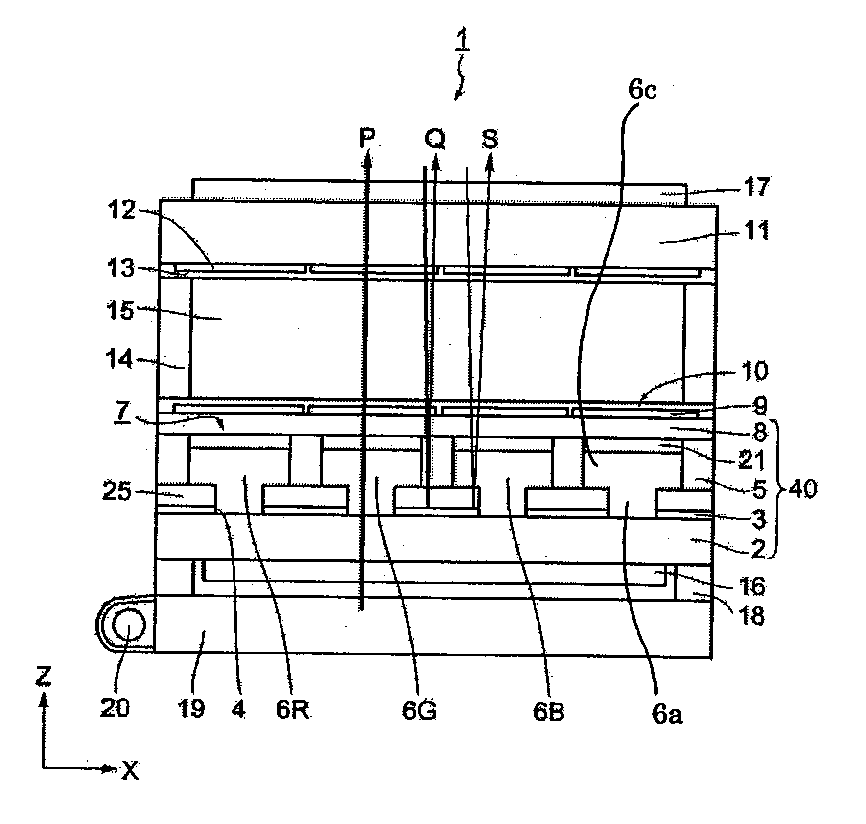
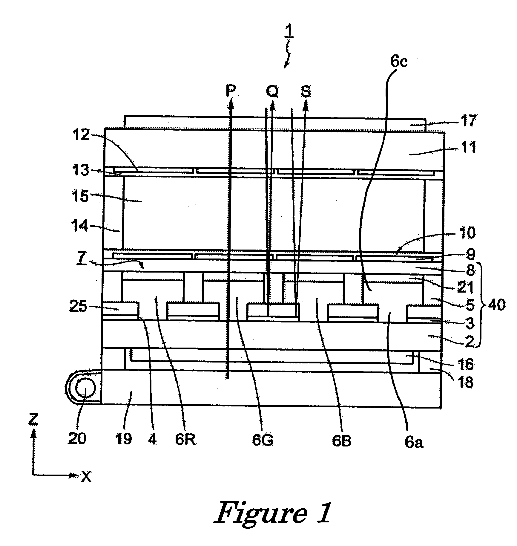
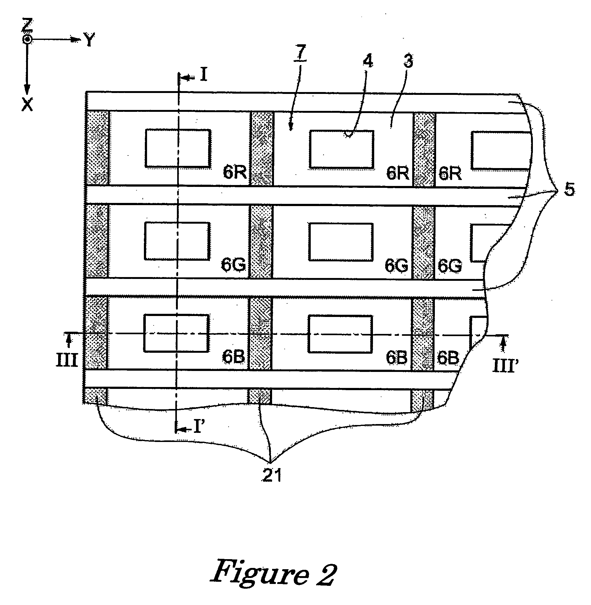
[0052]FIG. 1 is a cross-sectional view of the semi light-transmissive reflecting liquid crystal display device according to the first embodiment of the present invention. In this cross-sectional view, the side of the liquid crystal 15 on which the light source (backlight) 20 is disposed is referred to as the back side, and the opposite side as the front side. The display is usually viewed from the front side. FIG. 2 is a diagram in which the positioning of boundary layers 5 and 21 with the colored layers 6 of the present invention is depicted from the front side. A grid is formed with light-transmissive colorless boundary layers 5 that extend in the direction of the Y-axis at a plurality of locations, and non light-transmissive colored boundary layers 21 that extend at a plurality of locations in the direction of the X-axis, which is orthogonal to the Y-axis. FIG. 1 is a diagram depicting a cross section (I-I′) of the colorless boundary layers 5, and FIG. 3 is a diagram depicting a ...

second embodiment

[0069] Referring now to FIG. 4-5, a liquid crystal display 30 in accordance with a second embodiment will now be explained. In view of the similarity between the first and second embodiments, the parts of the second embodiment that are identical to the parts of the first embodiment will be given the same reference numerals as those of the first embodiment.

[0070] The second embodiment of the present invention will next be described referring to FIGS. 2 and 4-5. FIG. 4 is a cross-sectional view depicting the semi light-transmissive reflecting liquid crystal display device 30 in accordance with the second embodiment of the present invention. As in the first embodiment, the side of the liquid crystal 15 on which the light source 20 is disposed is referred to as the back side, and the opposite side as the front side in this cross-sectional view. A grid is formed with light-transmissive colorless boundary layers 5 that extend in the direction of the Y-axis at a plurality of locations, an...

third embodiment

[0110] The liquid crystal display device 300 depicted in FIG. 12 is a display device provided with a TFD (Thin Film Diode), which is a two-terminal element, as a switching element. The liquid crystal display device 300 is provided with a polarizing plate 320A, a polarizing plate 320B, a color filter substrate 310, an opposing substrate 312, a liquid crystal layer 314, and a light source 316. The liquid crystal layer 314 is positioned between the color filter substrate 310 and the opposing substrate 312. The color filter substrate 310 is also positioned between the liquid crystal layer 314 and the light source 316. The color filter substrate 310, the liquid crystal layer 314, and the opposing substrate 312 are positioned between the polarizing plate 320A and the polarizing plate 320B. The color filter substrate 310 is also sometimes referred to simply as the “color filter.”

[0111] The color filter substrate 310 includes a light-transmissive substrate 332; a reflective portion 326; a t...


PUM


Abstract

A color filter 40 has a light-transmissive substrate 2, a reflecting layer 3 formed on the back substrate 2 and provided with openings 4, boundary layers 5 and 21 formed on the reflecting layer 3, and a plurality of coloring layers 6 enclosed by the boundary layers 5 and 21. A transparent coat layer 25 is provided between the reflecting layer 3 and the boundary layers 5 and 21. A step is formed between the openings 4 and the transparent coat layer 25. The coloring layers 6 are formed by applying the droplets 150 of colored fluid to the openings 4 first, and then to the transparent coat layer 25. The difference in color saturation of the color filter 40 in a reflective display mode and a transmissive display mode is reduced. Also, a liquid material is appropriately applied to the color filter 40, to enhance color balance.

Description

BACKGROUND OF THE INVENTION [0001] 1. Field of the Invention [0002] The present invention relates to a color filter that functions both in a reflective display mode and a transmissive display mode, a method of manufacturing such color filter, a method of depositing a liquid material to manufacture such color filter, a display device having such color filter, a method of manufacturing a liquid crystal display device having such color filter, an electro-optic device having such color filter, an electronic instrument having such color filter, and to a method of manufacturing such electronic instrument. [0003] 2. Background Information [0004] A liquid crystal display device is known to be equipped with a color filter that functions both as a reflective display by using external light and a transmissive display by using a backlight. When such conventional liquid crystal display device functions as a reflective display, colored light is obtained when the incoming light from outside passes...

Claims


Application Information

Patent Timeline
IPC IPC(8): B05C5/00B41J2/01B41J2/145G02B5/20G02F1/13G02F1/1335G03B21/14G09F9/00
CPCB41J2/145B41J2202/09G02F1/133555G02B5/201G02F1/133516B41J2202/20G02F1/1335G02F1/13
Inventor KATAGAMI, SATORUUSHIYAMA, TOSHIHIROARUGA, HISASHI
Owner SEIKO EPSON CORP
Why Eureka
Try Eureka