Illuminating system and projecting apparatus

A lighting system and projection device technology, which is applied in lighting devices, lighting applications, projection devices, etc., can solve the problems of large overall optical path volume, increased cost, and reduced service life of projection devices, and achieve reduced volume, better color balance, and reduced cost effect

Inactive Publication Date: 2013-04-10
CORETRONIC
View PDF12 Cites 10 Cited by
  • Summary
  • Abstract
  • Description
  • Claims
  • Application Information

AI Technical Summary

Problems solved by technology

However, the long-term irradiation of the diffusion sheet by the blue laser will have reliability problems, thereby reducing the service life of the projection device.
In addition, in the prior art, the design of blue laser penetrating optical elements will be combined with other optical elements to form a complete optical path, which tends to make the overall optical path occupy a large volume, making it difficult to reduce the overall volume of the projection device
In addition, the use of other optical components is also likely to lead to cost increases
Furthermore, the color of the blue laser is more blue-purple than true blue, which is more likely to affect the color quality of the image screen of the projection device

Method used


Image

  • Illuminating system and projecting apparatus
  • Illuminating system and projecting apparatus
  • Illuminating system and projecting apparatus

Examples


Embodiment Construction

[0016] The aforementioned and other technical content, features and effects of the present invention will be clearly presented in the following detailed description of preferred embodiments in conjunction with the accompanying drawings. The directional terms mentioned in the following embodiments, such as: up, down, left, right, front or back, etc., are only referring to the directions of the drawings. Accordingly, the directional terms are used to illustrate and not to limit the invention.

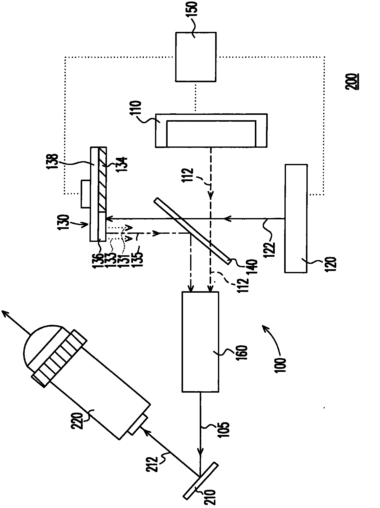
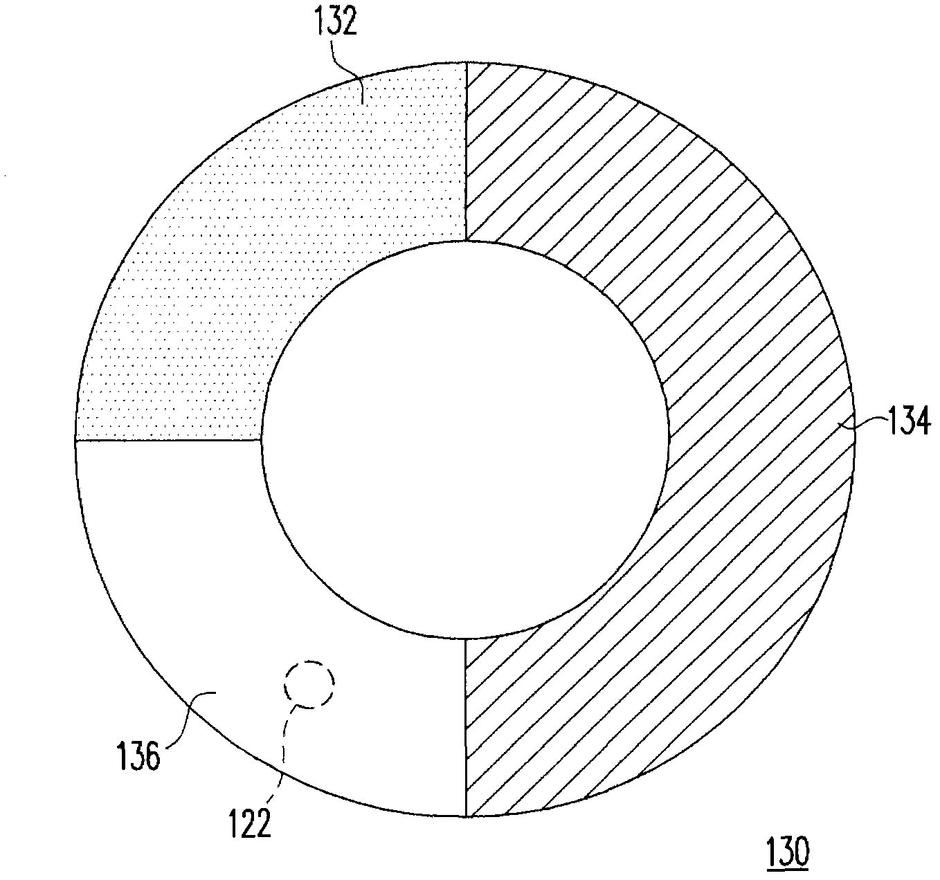
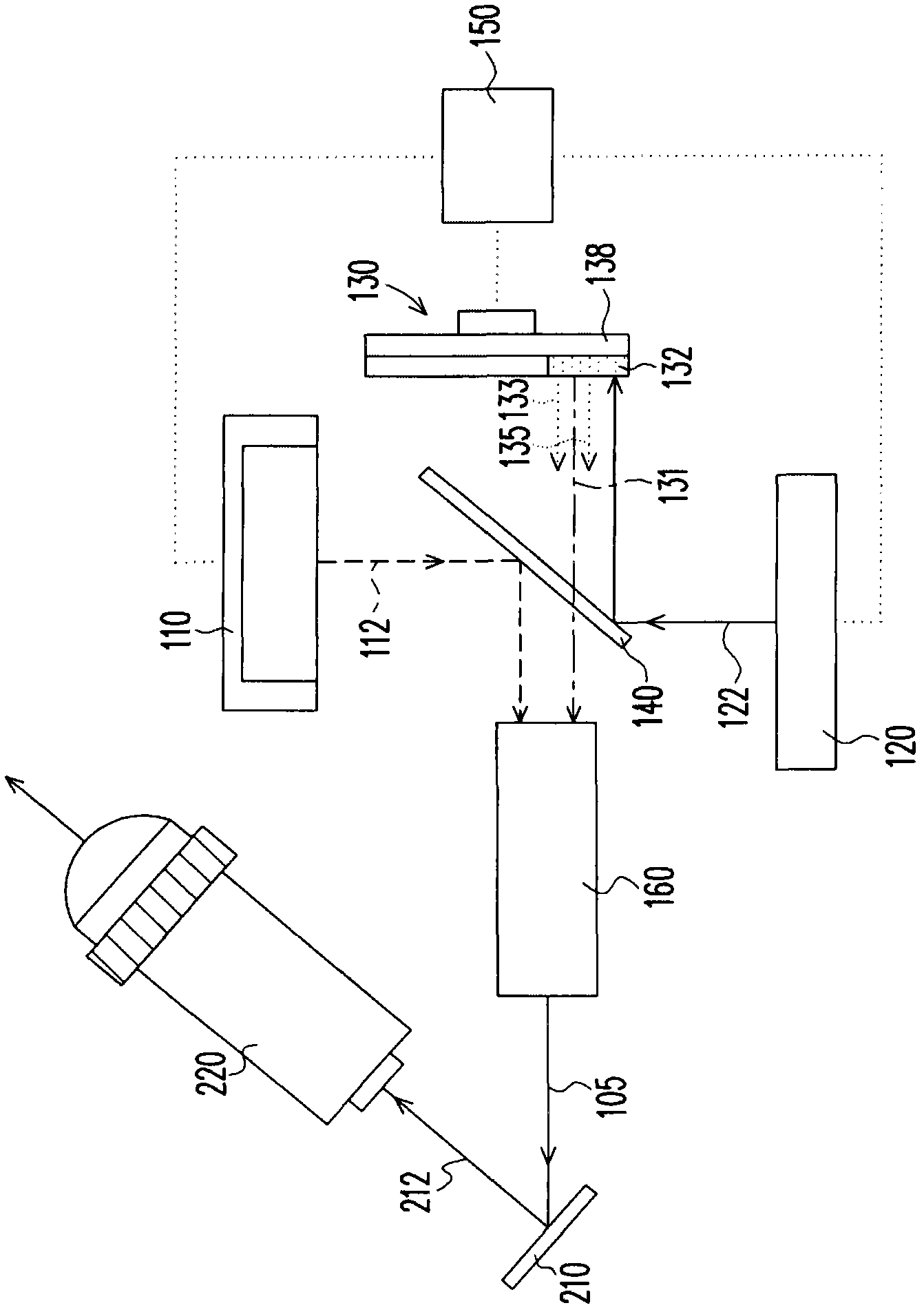
[0017] figure 1 is a schematic diagram of a projection device according to an embodiment of the present invention, and figure 2 for figure 1 Front view of the fluorescence module in . Please refer to figure 1 and figure 2 , the projection device 200 of this embodiment includes an illumination system 100 , a light valve 210 and a projection lens 220 . The lighting system 100 includes a blue incoherent light source 110 , a coherent light source 120 , a fluorescent module 130 and a l...


PUM


Abstract

An illuminating system comprises a blue incoherent light source, a coherent light source, a fluorescent module and a light-combined unit. The blue incoherent light source is used for sending out a blue incoherent light beam. The coherent light source is used for sending out a coherent light beam, wherein the wavelength of the coherent light beam is smaller than or equal to that of the blue incoherent light beam. The fluorescent module is provided with a first color fluorescent area and a second color fluorescent area. The first color fluorescent area and the second color fluorescent area take turns to cut into a transmitting path of the coherent light beam to respectively change the coherent light beam into a first color light beam and a second color light beam. The light-combined unit is arranged on the transmitting paths of the blue incoherent light beam, the first color light beam and the second color light beam to combine the blue incoherent light beam, the first color light beam and the second color light beam. The invention further provides a projecting apparatus.

Description

technical field [0001] The invention relates to a light source and a display device, and in particular to an illumination system and a projection device. Background technique [0002] Projection devices generally use ultra high pressure lamps (UHP lamps) as light sources, and in recent years there is also a trend of using light-emitting diodes (light-emitting diodes, LEDs) as light sources. Although light-emitting diodes have the advantages of fast response, no warm-up time, energy saving, environmental protection, and long service life, the brightness of light-emitting diodes is lower than that of high-pressure mercury lamps, making it difficult to apply light-emitting diodes to high-brightness in the prior art. projection device. [0003] One existing technique is to use a pure laser source to excite phosphors to produce multiple colors. In this prior art, the blue light is a blue laser that passes through an optical element. Due to the high coherence of the blue laser,...

Claims


Application Information

Patent Timeline
Patent Type & Authority Applications(China)
IPC IPC(8): G03B21/20G03B21/14G02B27/10F21S19/00
CPCG02B27/102G03B21/2013G03B21/204
Inventor 曾志能
Owner CORETRONIC
Why Eureka
Try Eureka