Intermediate adapter and camera system

a technology of interchangeable lenses and adapters, applied in the field of intermediate adapters, can solve the problems of affecting the performance of the camera system, the rear end portion of the interchangeable lens and the quick return mirror may interfere with each other, and the same size of the electronic image pickup elements, etc., to achieve the effect of convenient mounting

Active Publication Date: 2005-02-03
CANON KK
View PDF5 Cites 75 Cited by
  • Summary
  • Abstract
  • Description
  • Claims
  • Application Information

AI Technical Summary

Benefits of technology

[0014] It is an object of the present invention to provide an intermediate adapter capable of mounting a plurality of interchangeable lenses having different protruding amounts toward an image plane from a mount reference surface to two types of cameras, namely a camera to which an interchangeable lens having a la

Problems solved by technology

However, since the electronic image pickup elements, such as a CCD sensor and a CMOS sensor, having the same size as the 35 mm silver halide films, are expensive, the image pickup elements (for example, image pickup elements having an APS-C size) smaller than the 35 mm films have been mainly used.
However, when the interchangeable lens having a short back focus is mounted on a body of the 35 mm film camera or a digital camera having an image circle larger than that of the interchangeable lens, the rear end portion of the interchangeable lens and the quick return mirror may interfere with each other.
Further, when an interchangeable lens only for a digital camera having a short back focus (having a small image circle) is arranged to be mounted on the camera body of a conventional camera system, there is a disadvantage in that a light flux does not reach the periphery

Method used


Image

  • Intermediate adapter and camera system
  • Intermediate adapter and camera system
  • Intermediate adapter and camera system

Examples


embodiment 1

[0040] [Embodiment 1]

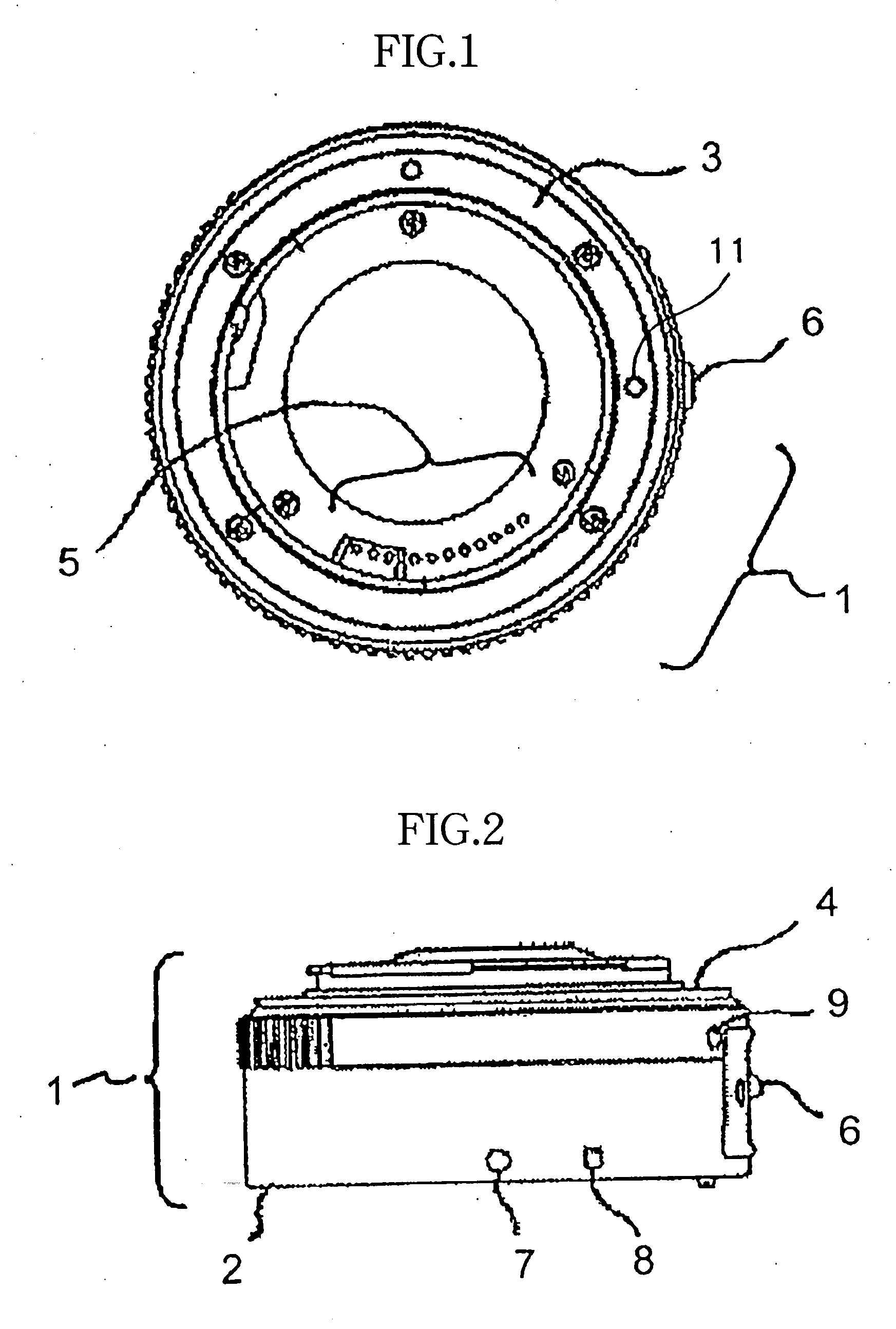
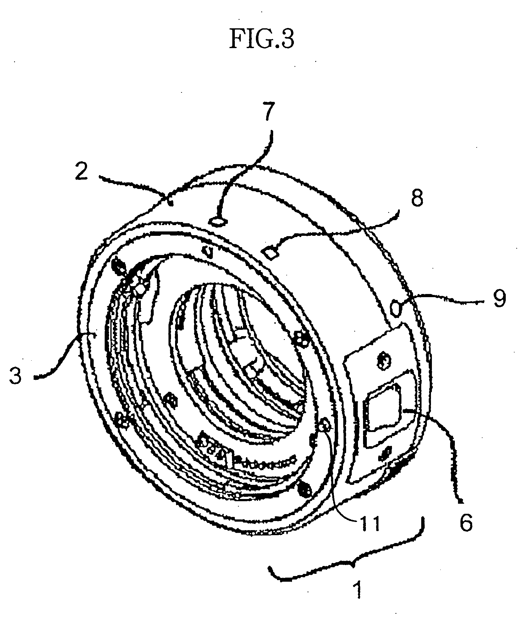
[0041]FIG. 1 is a front view of an intermediate adapter allowing close-up image-taking, which is Embodiment 1, FIG. 2 is a top view of the intermediate adapter, and FIG. 3 is a perspective view of the intermediate adapter.

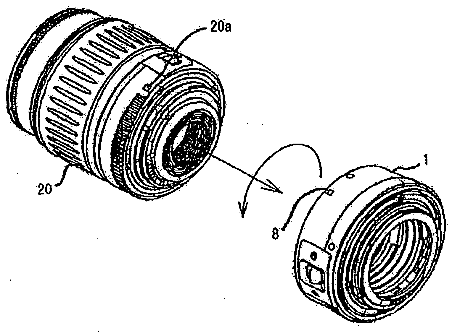
[0042] In FIGS. 1, 2, and 3, reference numeral 1 denotes an intermediate adapter, reference numeral 2 denotes an adapter body, reference numeral 3 is a lens-side mount, and reference numeral 4 is a camera-side mount. On the lens-side mount 3 and the camera-side mount 4 respectively, a bayonet lug, which can be engaged with a bayonet lug provided on a mount of an interchangeable lens and a bayonet lug provided on a mount of a camera, is provided.

[0043] Reference numeral 5 denotes electrical connection pins on the interchangeable lens side and the camera side, and the electrical connection pins 5 are used for transmitting electric signals for control. Reference numeral 6 denotes a lock release lever for releasing the locking of a lock pin 11 wh...

embodiment 2

[0050] [Embodiment 2]

[0051] The interchangeable lens, the camera, and the intermediate adapter described in Embodiment 1 will be denoted by new reference numerals and be described in detail as Embodiment 2 with reference to FIGS. 8 to 21. Here, first and second cameras will be described as digital cameras comprising image pickup elements. Further, in the following description, “front” denotes the object side, and “rear” denotes the image plane side or the image pickup element side.

[0052]FIGS. 11, 12, and 13 show a first camera (a camera body) 201 constituting a camera system according to Embodiment 2. A ring-shaped mount 202 for mounting a first interchangeable lens or an intermediate adapter, as will be described later, is located at the front surface of the first camera 201. The front end surface of the mount 202 serves as a reference surface (mount reference surface) 202a when the first interchangeable lens or the intermediate adapter is mounted thereon.

[0053] At a position retr...


PUM


Abstract

The present invention provides an intermediate adapter capable of being mounted on a first camera on which a first interchangeable lens is mounted and a second camera on which the first interchangeable lens and a second interchangeable lens are mounted. The second interchangeable lens includes a protruding portion protruding toward an image plane from its mount reference surface whose protruding amount is larger than that of the first interchangeable lens and has a flange back equal to that of the first interchangeable lens. The first camera has a first wall portion inside its mount and prevents mounting of the second interchangeable lens by the protruding portion of the second interchangeable lens contacting the first wall portion. The second camera includes a second wall portion provided inside its mount at a position retreated from the protruding portion of the second interchangeable lens.

Description

BACKGROUND OF THE INVENTION [0001] 1. Field of the Invention [0002] The present invention relates to an intermediate adapter that is used in a camera system including a plurality of cameras having a same mount structure and interchangeable lenses having different protruding amounts toward an image plane from its mount reference surface and that is mounted between a camera and a interchangeable lens. [0003] 2. Description of Related Art [0004] In recent advancements in applying digital technologies to cameras, single-lens reflex digital cameras have been proposed, in which 35 mm silver halide films are replaced with electronic image pickup elements, such as a CCD sensor and a CMOS sensor, while maintaining the uniformity of a mount structure to allow a conventional group of interchangeable lenses to be mounted and used in a single-lens reflex camera system, a lens of which can be replaced. However, since the electronic image pickup elements, such as a CCD sensor and a CMOS sensor, ha...

Claims


Application Information

Patent Timeline
IPC IPC(8): G02B7/02G02B7/14G03B17/14G03B17/56
CPCG03B17/14G03B17/565
Inventor SUGITA, JUNTAMURA, MASAHISAKOYAMA, ATSUSHI
Owner CANON KK
Why Eureka
Try Eureka