Camera body

Active Publication Date: 2005-02-03
PENTAX RICOH IMAGING CO LTD
View PDF14 Cites 13 Cited by
  • Summary
  • Abstract
  • Description
  • Claims
  • Application Information

AI Technical Summary

Benefits of technology

[0008] The present invention provides a camera which incorporates a camera body making it possible to

Problems solved by technology

Such thermal distortion occurs unevenly because the mirror box is fixed to the main body only at finite number of points to thereby cause a variation in amount of thermal distortion of the mirror box at different portions thereof, or because there is a difference in amount of thermal distortion between the portions of the mirror box which are different in direction of resin flow at the process of molding the mirror box in the case where the mirror box is molded of resin.
If such a difference in amount of thermal distortion occurs, high-quality images (tightly focused images) cannot be obtained due to such reasons as the mounting surface of the lens mount on the camera body to which a photographing lens is detachably attached becoming nonparallel to a focal plane (a film surface or an imaging surface of an image pick-up device), the axial position of the focal plane (or back focal distance) varying, an image formed on a picture plane partly becoming out-of-focus, and defocusing occurring i

Method used


Image

  • Camera body
  • Camera body
  • Camera body

Examples


first embodiment

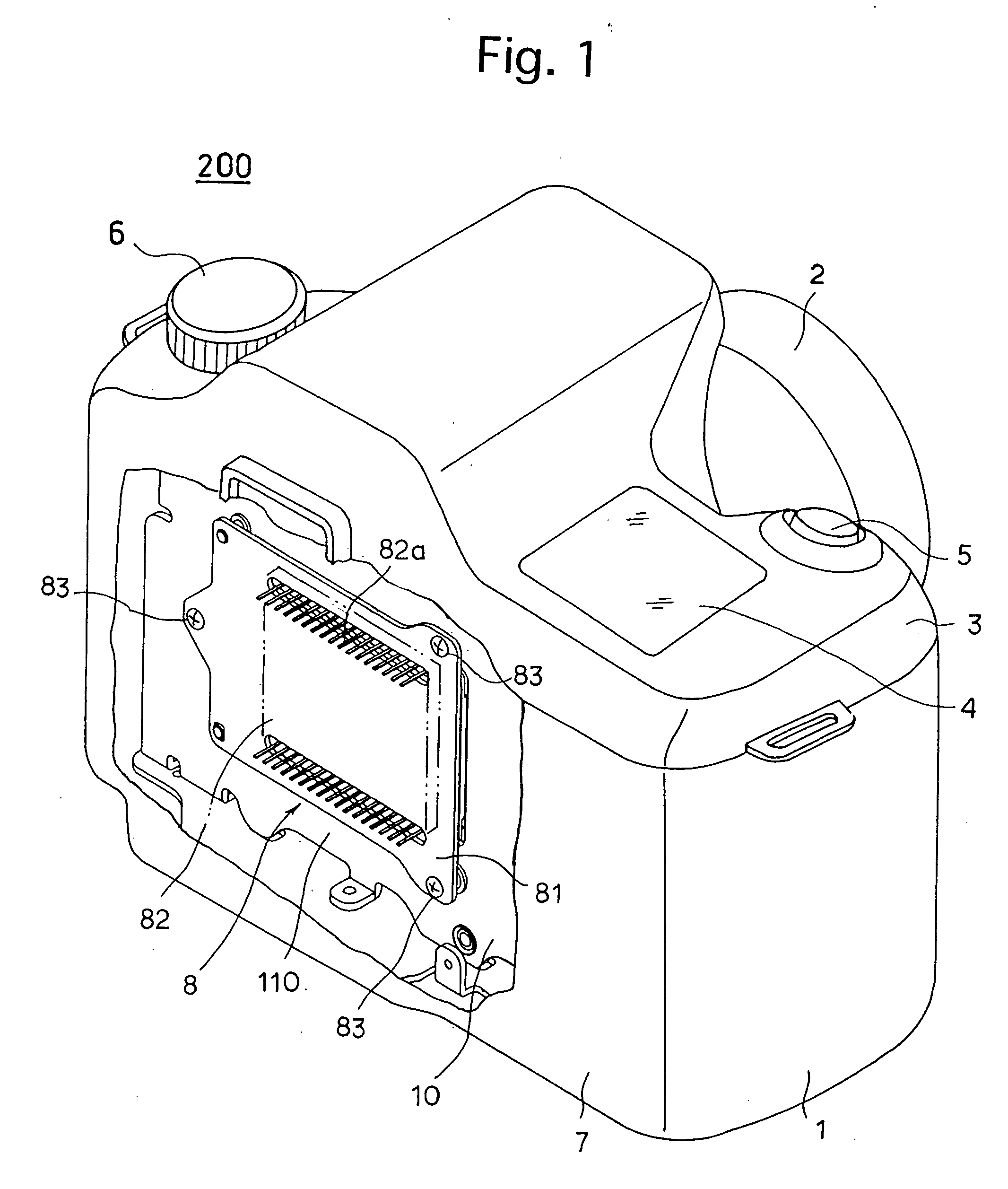
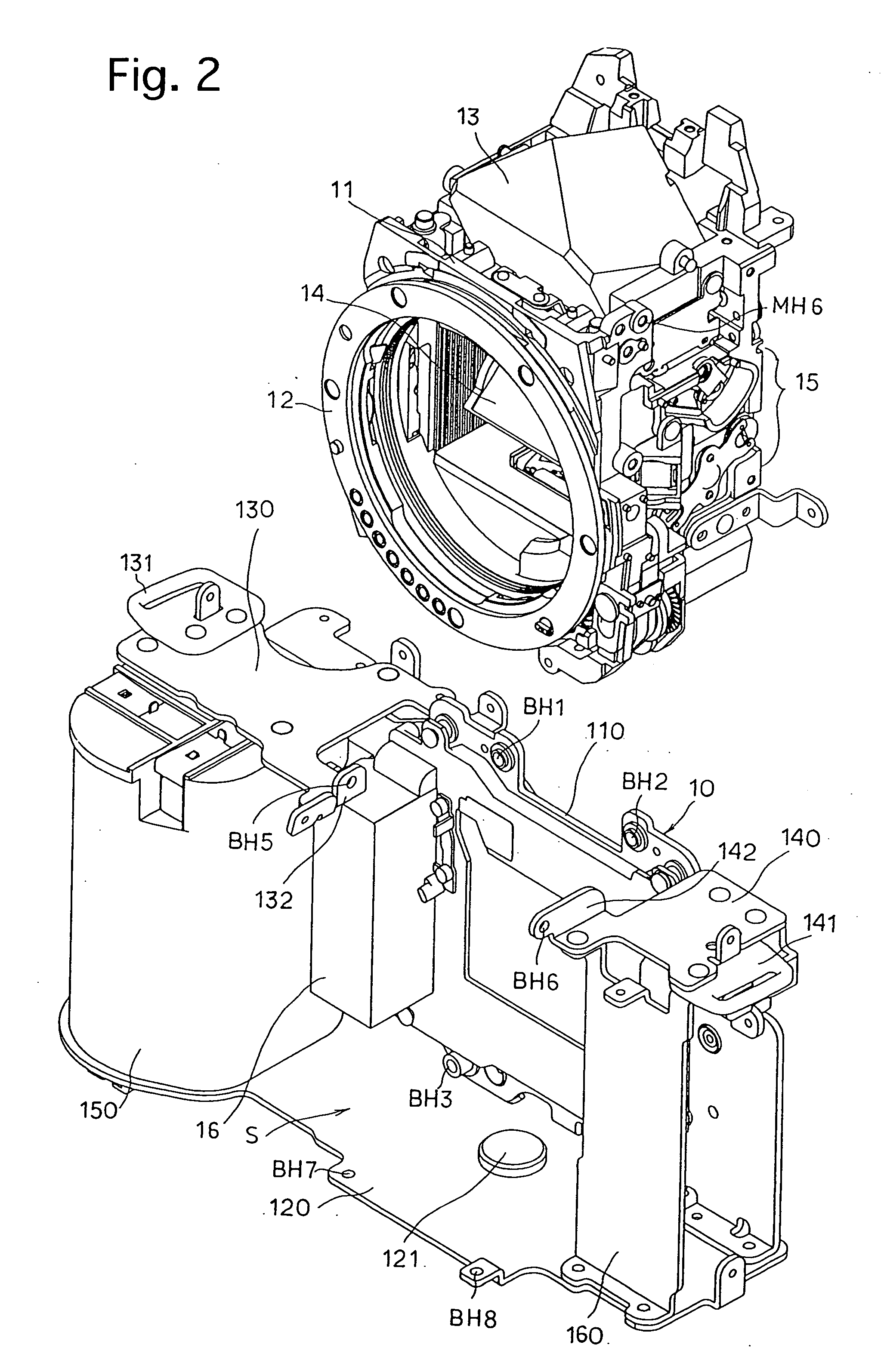
[0037]FIG. 1 shows a digital camera according to the present invention. The digital camera 200 that is constructed as an SLR digital camera is provided with an interchangeable photographing lens 2 which is detachably attached to the front of a camera body 1. The digital camera 200 is provided on a top cover 3 of the camera body 1 with an LCD indicating portion 4, a release button 5 and a select dial (dial switch) 6. The digital camera 200 is provided on a back cover 7, a portion of which is broken away for clarity in FIG. 1, with an LCD monitor and various switches (all of which are not shown in FIG. 1). The digital camera 200 is provided therein inside the back cover 7 (i.e., inside the camera body 1) with a CCD unit (image sensor unit) 8 including a large CCD image sensor (CCD chip). The CCD unit 8 is fixed to a main body 10 positioned inside the camera body 1 in an internal space thereof behind a mirror box 11 (not shown in FIG. 1) provided in the camera body 1, so that an imagin...

second embodiment

[0049] [Second Embodiment]

[0050]FIGS. 9A and 9B schematically show the left side of the mirror box 11 in a second embodiment of the camera body (main body 10 and mirror box 11) of the digital camera according to the present invention. In this embodiment, a main body corresponding to the main body 10 is provided with a left-side cantilever 130A which projects forward in the optical axis direction from the back member 110 of the main body. The left-side cantilever 130A is fixed to the mirror box 11 by a left set screw N11 in the vicinity of the front end of the left-side cantilever 130A at a portion thereof whose vertical position is identical to the vertical position of the optical axis of the photographing lens 2. Likewise, the main body is provided with a right-side cantilever (not shown) which projects forward in the optical axis direction from the back member 110 of the main body, and the right-side cantilever is fixed to the mirror box 11 by a right set screw N12 in the vicinity...


PUM


Abstract

A camera which includes a camera body includes a main body and a mirror box fixed to the main body. The mirror box and the main body are made of a first material having a first thermal expansion coefficient and a second material having a second thermal expansion coefficient, respectively, the second thermal expansion coefficient being smaller than the first thermal expansion coefficient. The mirror box is fixed to the main body by at least two fixing devices symmetrically disposed with respect to an optical axis.

Description

BACKGROUND OF THE INVENTION [0001] 1. Field of the Invention [0002] The present invention relates to a camera in which a camera body thereof is composed of a main body and a mirror box fixed to the main body, and more specifically relates to such a camera in which the mirror box is made of a material having a relatively high thermal expansion coefficient. [0003] 2. Description of the Related Art [0004] An SLR camera system in which a camera body is composed of a main body and a mirror box, which are molded independently of each other, is known in the art. In the camera body of this type of SLR camera system, the mirror box which accommodates a reflecting mirror such as a quick-return mirror or a pellicle mirror and is generally equipped with components such as a lens mount, a shutter charge mechanism and a viewfinder optical system, thus required to be formed in a complicated shape, is often die-cast in aluminum or made of a glass fiber reinforced plastic (GFRP). On the other hand, ...

Claims


Application Information

Patent Timeline
IPC IPC(8): G03B17/02G03B19/12H04N5/225
CPCG03B17/02G03B19/12H04N2101/00H04N5/2254H04N5/2253H04N23/55H04N23/54H04N23/51
Inventor KUROSAWA, YUICHI
Owner PENTAX RICOH IMAGING CO LTD
Why Eureka
Try Eureka