Aerodynamic vented rotor

Inactive Publication Date: 2007-11-15
FORD GLOBAL TECH LLC
View PDF26 Cites 5 Cited by
  • Summary
  • Abstract
  • Description
  • Claims
  • Application Information

AI Technical Summary

Benefits of technology

[0008] Another aspect of heat transfer for automotive brakes is minimizing uneven thermal distortion of the rotor plates encompassing the vent. Uneven distortion, often referred to as “coning,” causes uneven wear of brake pads and rotors, and subsequently sub-optimized brake performance. In conventional rotors, the central hub or hat section is connected to either the rotor's outboard disc or its inboard disc. Whichever disc the hat section extends from is cooled more effectively because the friction heat generated in the disc is transferred through the hat section in addition to being cooled by the rotor vents. The other disc is, for the most part cooled only by the vents. Because one disc is cooled more effectively, the discs have an uneven heat distribution and therefore uneven thermal distortion from heat, resulting in coning.
[0009] The present invention provides two design features for improving disc brake heat transfer. First, using an airfoil shape for the rotor fins to reduce flow separation and increase convective heat transfer efficiency. The airfoil shape is preferably a NACA airfoil series shape, as is

Problems solved by technology

Conventional vent geometry often includes straight lines and arcs, which undesirably cause flow separation when air flows through vents.
Uneven distortion, often referred to as “coning,” causes uneven wear of brake pads

Method used


Image

  • Aerodynamic vented rotor
  • Aerodynamic vented rotor
  • Aerodynamic vented rotor

Examples


Example

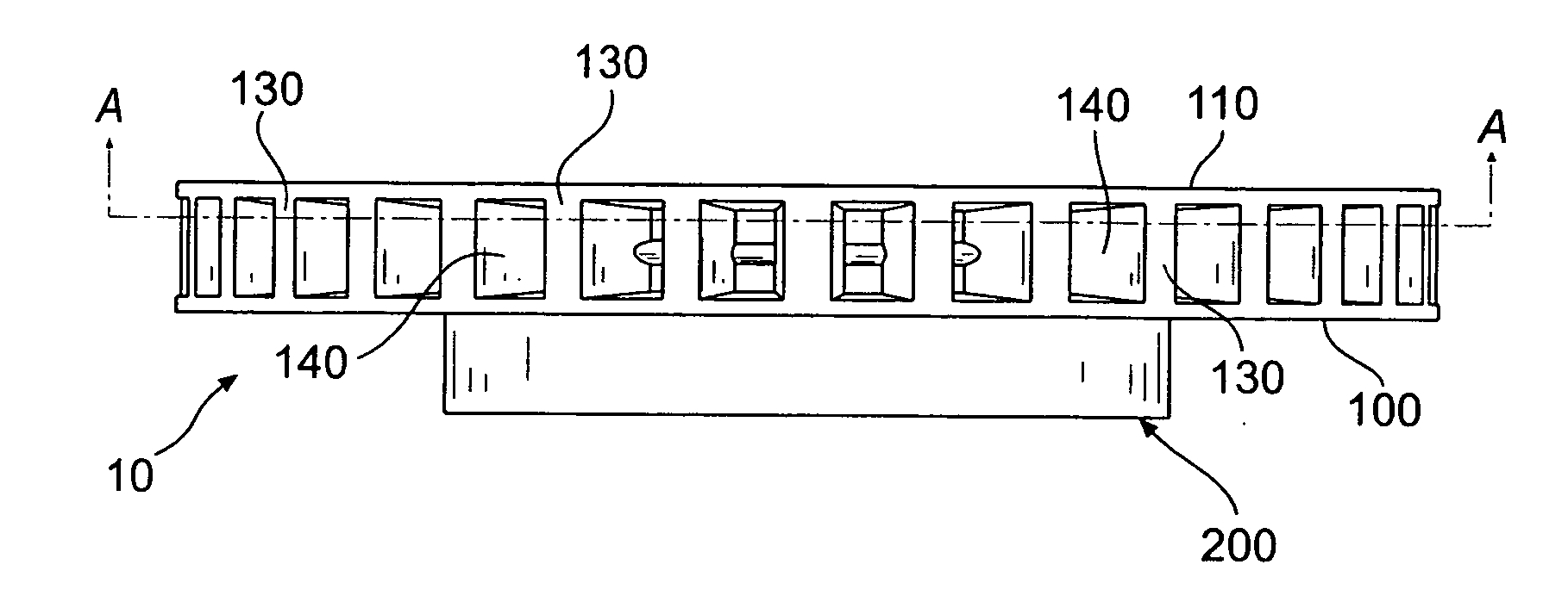
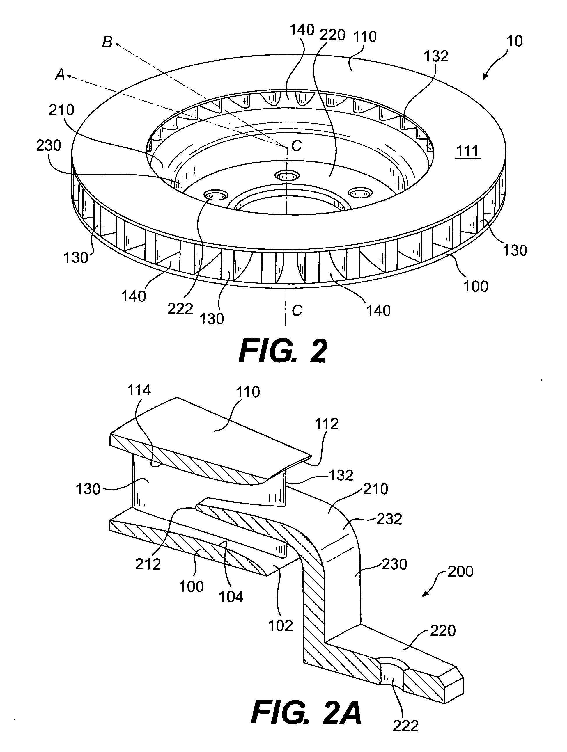
[0024] As shown in FIG. 1, an aerodynamic vented rotor 10 of the invention includes an outboard disc 100 and an inboard disc 110. The outboard disc 100 and the inboard disc 110 are preferably parallel annular discs that are spaced from one another. Outboard disc 100 is what a user might see from a location external to (outside of) the vehicle when looking into the vehicle's wheel. The outboard disc 100 includes a friction surface 101 (see FIG. 3B) and the inboard disc 110 includes a friction surface 111 (see FIGS. 2 and 3C). The friction surfaces 101, 111 are preferably maintained adjacent to brake pads of a brake caliper (not shown). During braking, brake pads commonly sweep along the friction surfaces 101, 111 to slow or stop the vehicle through controlled slippage. Thus, friction surfaces 101, 111 are heat dissipating surfaces during vehicle braking.

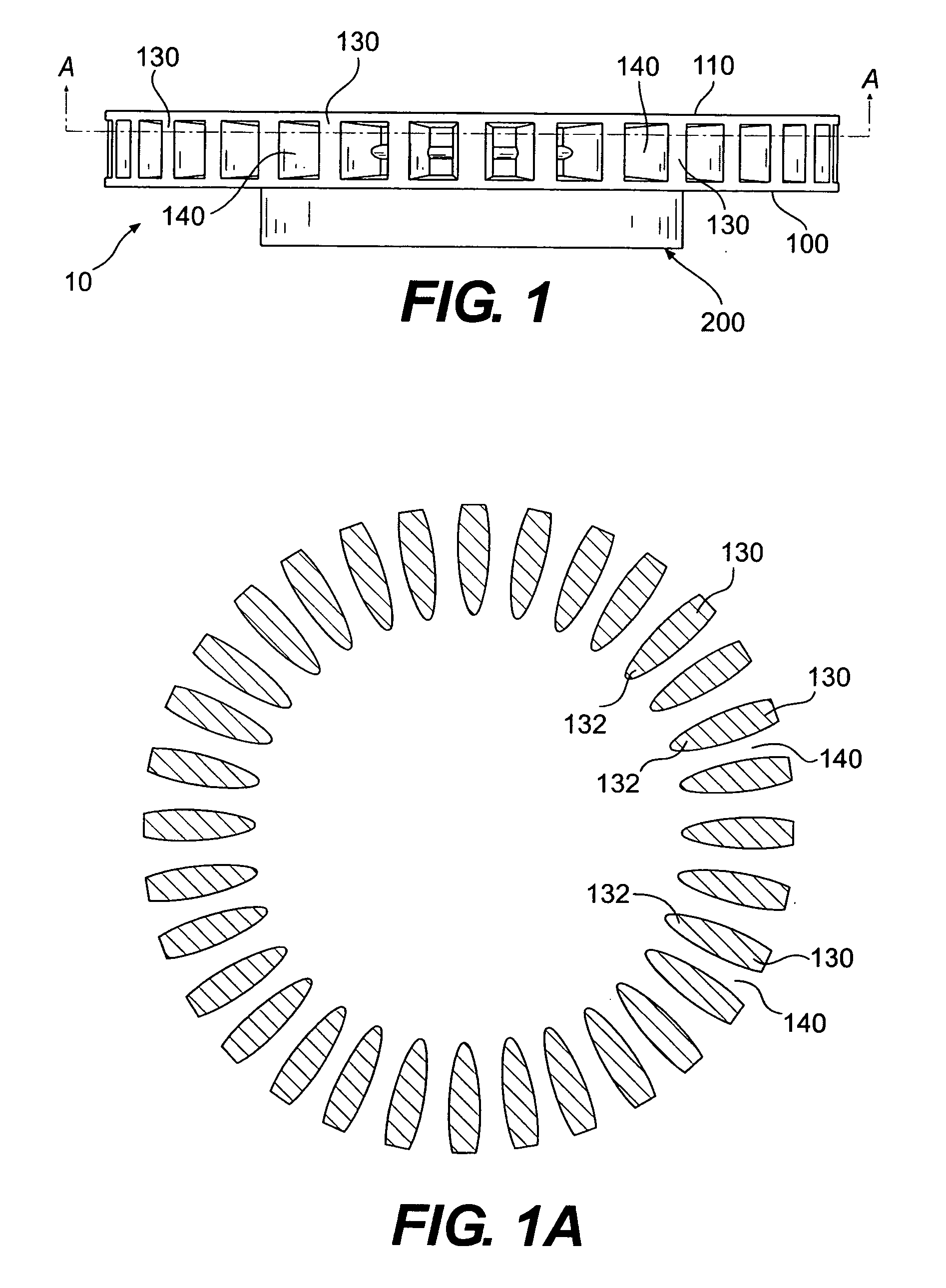
[0025] The outboard disc 100 and the inboard disc 110 are spaced from one another by vanes or fins 130. Vents 140 extend between th...


PUM


Abstract

An aerodynamic vented rotor comprises an outboard disc, an inboard disc spaced from the outboard disc, and fins extending between the outboard disc and the inboard disc and defining vents therebetween. The fins have an airfoil-shaped cross section with a leading edge facing radially inwardly on the rotor. The fins constitute an inner core, and a hat section extends from the inner core of the rotor.

Description

BACKGROUND OF THE INVENTION [0001] 1. Field of Invention [0002] This invention relates to the field of vented disc rotors. More specifically, this invention relates to a vented disc rotor having airfoil-shaped fins and / or an anti-coning center core. [0003] 2. Background [0004] Many braking systems include a rotor attached to one or more of the vehicle wheels for rotation therewith, and a caliper assembly secured to a non-rotating component of the vehicle, such as the vehicle frame. A typical rotor includes an annular peripheral section having frictional surfaces disposed on opposite sides and a central hub or hat section having fasteners for securing the wheel thereto. The caliper assembly typically includes a pair of brake pads disposed adjacent to the rotor friction surfaces, and a movable piston operatively connected to one or more of the brake pads. When the driver brakes the vehicle, hydraulic, electric, or pneumatic forces move the piston, which clamps the pads against the fri...

Claims


Application Information

Patent Timeline
IPC IPC(8): F16D65/827
CPCF16D2065/1328F16D65/12
Inventor HSU, FRANKOAKWOOD, CHRIS
Owner FORD GLOBAL TECH LLC
Why Eureka
Try Eureka