Stop apparatus, a lens and a video camera having the stop apparatus

a technology of stop apparatus and stop aperture, which is applied in the direction of cameras, television systems, instruments, etc., can solve the problems of reducing the diameter of the stop aperture, the configuration of the nd filter is complicated, and the resolving power is reduced, so as to reduce the contrast of an object, reduce the resolving power, and not cause uneven amount of light.

Inactive Publication Date: 2005-02-03
TAMRON
View PDF5 Cites 6 Cited by
  • Summary
  • Abstract
  • Description
  • Claims
  • Application Information

AI Technical Summary

Benefits of technology

[0024] According to this arrangement, it is possible to realize a video camera having a lens for an optical instrument comprising a stop apparatus constituted so that it does not cause the reduction of resolving power (reduction of contrast of an object) and does not cause unevenness of amount of light in an imaging plane.
[0025] Summing up the effects of the present invention, the stop apparatus of the present invention does not cause the reduction of resolving power (reduction of contrast of an object) and does not cause unevenness of amount of light in an imaging plane.
[0026] It is possible to provide a stop apparatus which can be manufactured easily and at a low cost.
[0027] In the lens for a video camera having the stop apparatus of the present invention as well as a video camera provided with the lens having the stop apparatus of the present invention, they do not cause the reduction of resolving power (reduction of contrast of an object) and do not cause unevenness of amount of light in an imaging-plane.

Problems solved by technology

There would be caused a problem that the resolving power is reduced due to generation of the diffraction effect of the stop aperture when the diameter of the stop aperture is extremely reduced.
Although it has been proposed an ND filter constituted such that the amount of ray transmission is reduced from the edge of the stop blade toward the edge of the notched portion in order to prevent generation of the diffraction effect, there are also caused a new problem that the configuration of the ND filter is complicated and thus manufacture of the ND filter is difficult.
Under the circumstances, there would be caused a problem that the resolving power is reduced (i.e. the contrast of an object is reduced) due to influence of the diffraction effect.
However the problem that the configuration of the ND filter is complicated and thus manufacture of the ND filter is difficult is still remained in this arrangement.

Method used


Image

  • Stop apparatus, a lens and a video camera having the stop apparatus
  • Stop apparatus, a lens and a video camera having the stop apparatus
  • Stop apparatus, a lens and a video camera having the stop apparatus

Examples


first embodiment

(1) First Embodiment

[0047] A first embodiment of the present invention will be hereinafter described.

[0048] (1•1) Structure of a Monitoring Camera

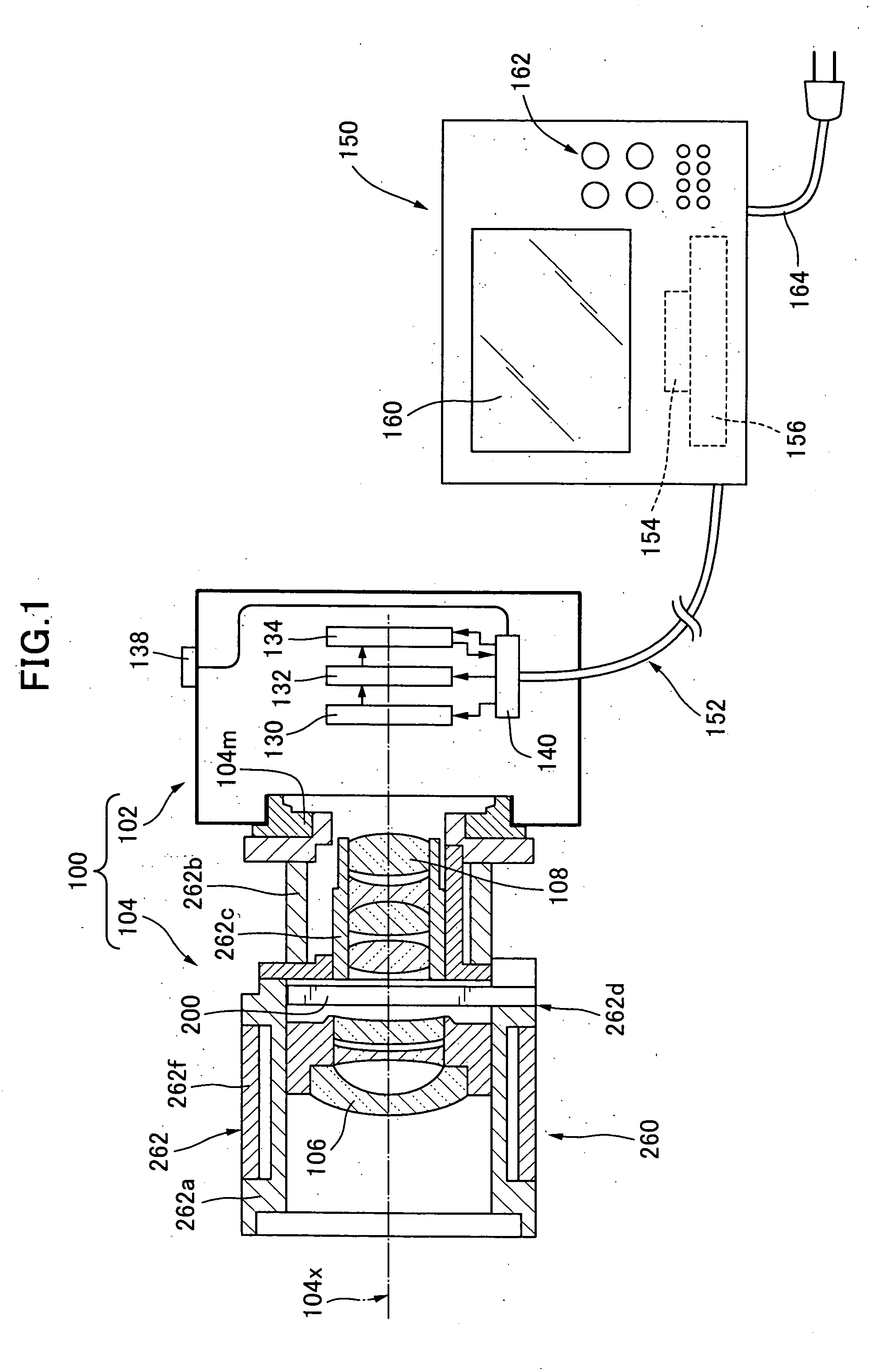
[0049] Firstly, the first embodiment of the present invention will be described with reference to the structure of the monitoring camera. As shown in FIG. 1, the monitoring camera 100 of the present invention comprises a camera body 102 for recording an image formed by luminous flux from an object, and an imaging lens 104 for leading the luminous flux from the object. The imaging lens 104 is detachably mounted on the camera body 102 via a lens mount 104m. As one modification, the imaging lens 104 may be rigidly secured on the camera body 102. The imaging lens 104 comprises an optical axis 104x of the imaging lens 104, an optical system of front group 106, an optical system of rear group 108, and a stop apparatus 200. The rear group optical system 108 constitutes a focus lens system arranged movably along the optical axis 104x of the imag...

second embodiment

(2) Second Embodiment

[0082] Then a second embodiment of the stop apparatus of the present invention will be described. In a following description, only a matter different from the first embodiment will be described. Accordingly matters not described herein should be applied to those previously described as to the first embodiment of the present invention.

[0083] (2•1) Structure of the Stop Apparatus

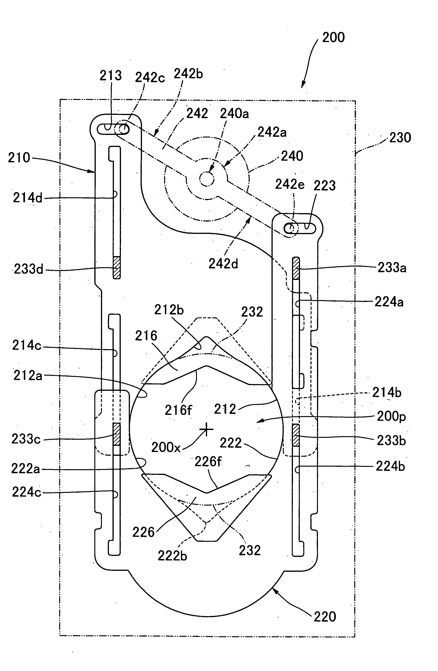
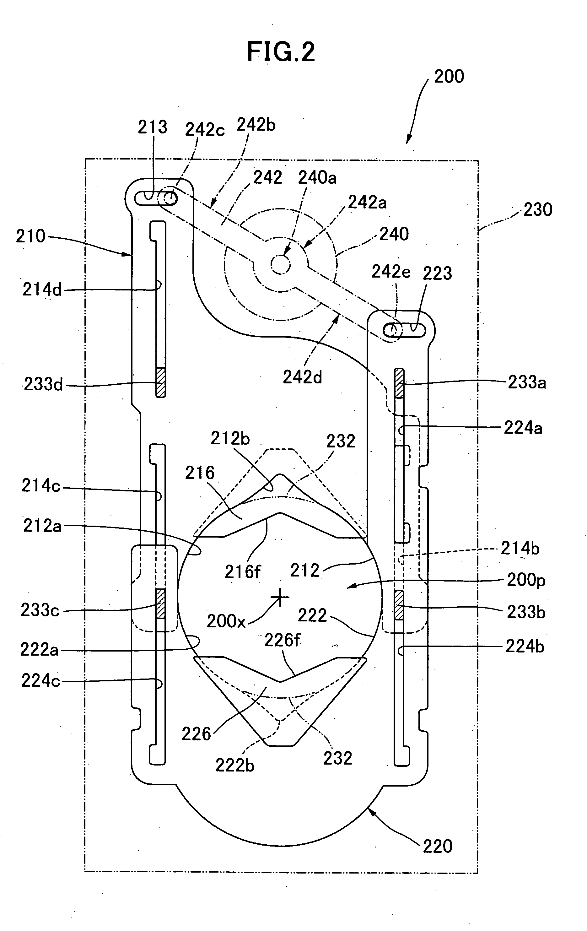
[0084] Then the structure of the stop apparatus of a second embodiment of the present invention will be described. With reference to FIG. 8, the stop apparatus 300 of the second embodiment comprises an upper blade 310, a lower blade 320, a stop unit plate 330 for supporting the upper and lower stop blades 310 and 320 to be linearly movable, and a galvanometer 340 for constituting actuator for linearly driving the upper and lower blades 310 and 320. A central axis 300x of the stop unit aperture 332 is arranged so that it corresponds to the optical axis 104x of the imaging lens 104 when th...


PUM


Abstract

There is provided a stop apparatus which does not cause the reduction of resolving power and does not cause unevenness of amount of light in an imaging plane even when it is an object of very high intensity. The stop apparatus of the present invention comprises an upper blade 210, a first ND filter 216 mounted on an aperture of the upper blade 210, a lower blade 220, a second ND filter 226 mounted on an aperture of the lower blade 220, a stop unit plate 230 movably supporting the upper and lower blades 210 and 220, and a galvanometer 240 for linearly driving the upper blade 210 in a first direction and for linearly driving the lower blade 220 in a second direction opposite to the first direction. The ray transmittance of the first ND filter 216 is different from that of the second ND filter 226 so as to prevent reduction of the contrast of object with reference to other object situated at a distance different from the object distance of the focused object.

Description

BACKGROUND OF THE INVENTION [0001] 1. Field of the Invention [0002] The present invention relates generally to a stop apparatus used for lens systems of optical instruments such as a video camera etc., and more particularly to a stop apparatus in which an optical filter is mounted on each of two stop blades having a notch for controlling an amount of light. In addition the present invention relates to a lens for a video camera into which the stop apparatus is incorporated. Furthermore, the present invention relates to a video camera having said lens. [0003] 2. Description of Background Art [0004] In usual a stop apparatus having two stop blades called as a Galvano type is used for a lens for a video camera such as a conventional monitoring camera. In these stop apparatus, an ND filter (neutral density filter) is stuck on at least one of the stop blades. The two-blade type stop apparatus is disclosed for example in Patent Document 1 noticed below. In the field of monitoring, a high s...

Claims


Application Information

Patent Timeline
Patent Type & Authority Applications(United States)
IPC IPC(8): G03B9/04G03B9/02G03B9/08G03B9/14H04N5/238
CPCG03B9/14G03B9/02
Inventor WATANABE, YUKOMURAMATSU, YUICHINAKAI, SEIGO
Owner TAMRON
Why Eureka
Try Eureka