Device for liquid treatment of wafer-shaped articles

Inactive Publication Date: 2005-02-03
LAM RES AG
View PDF21 Cites 16 Cited by
  • Summary
  • Abstract
  • Description
  • Claims
  • Application Information

AI Technical Summary

Benefits of technology

[0024] The mask and the wafer-shaped article are moved apart from one another by one such distance spacing means such that the liquid which is found in the area in between can be removed again. It is advantageous if the distance changing means can increase the distance by at least 0.2 mm, preferably at

Problems solved by technology

The defect of this system is that the area to be treated is not exactly

Method used


Image

  • Device for liquid treatment of wafer-shaped articles
  • Device for liquid treatment of wafer-shaped articles
  • Device for liquid treatment of wafer-shaped articles

Examples


third embodiment

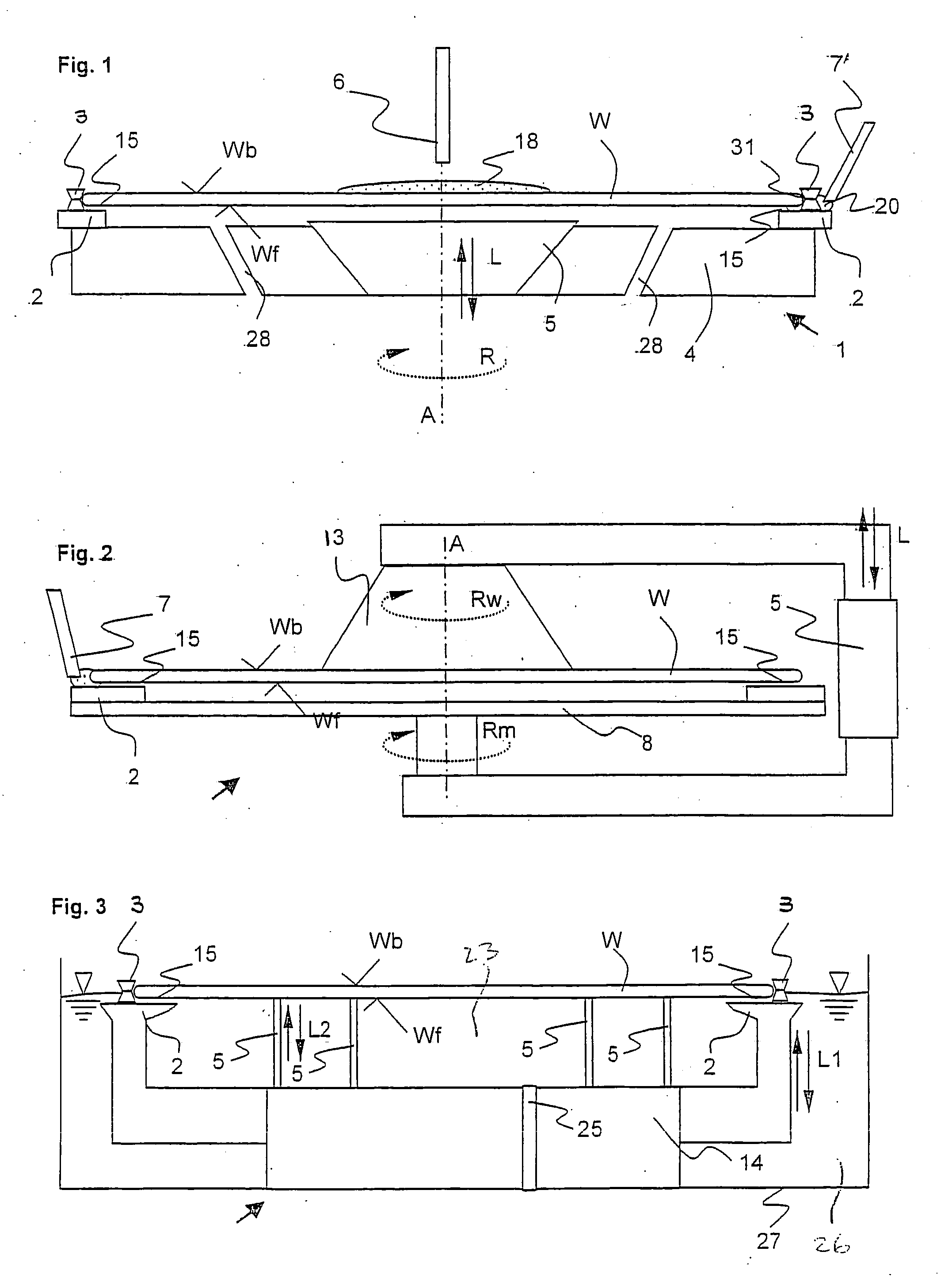
[0043]FIG. 3 shows a The device 1 consists of a bath tank 27 in which there is a pot-shaped carrier 14. The space 23 within the carrier is sealed against the bath 26 which is located between the carrier and bath tank. The carrier 14 can be lifted from the bath 26 using the lifting mechanism. The upper edge of the carrier has the shape of a ring 2 which represents the mask, with a surface which faces the wafer W and which is plane-parallel to its surfaces Wf. On this ring 2 (mask) there are pins 3 with notches which keep the wafer at a defined distance to the mask, by which a gap 15 forms. The carrier 14 with the wafer W located on it is lowered into the bath (L1) so far that the liquid level is located somewhat above the ring so that the wafer edge is wetted. The liquid is pulled by capillary forces into the gap 15 between the wafer and mask. To prevent the penetration of liquid into the space 23 within the carrier as a result of the negative pressure in it, the space is connected ...

fourth embodiment

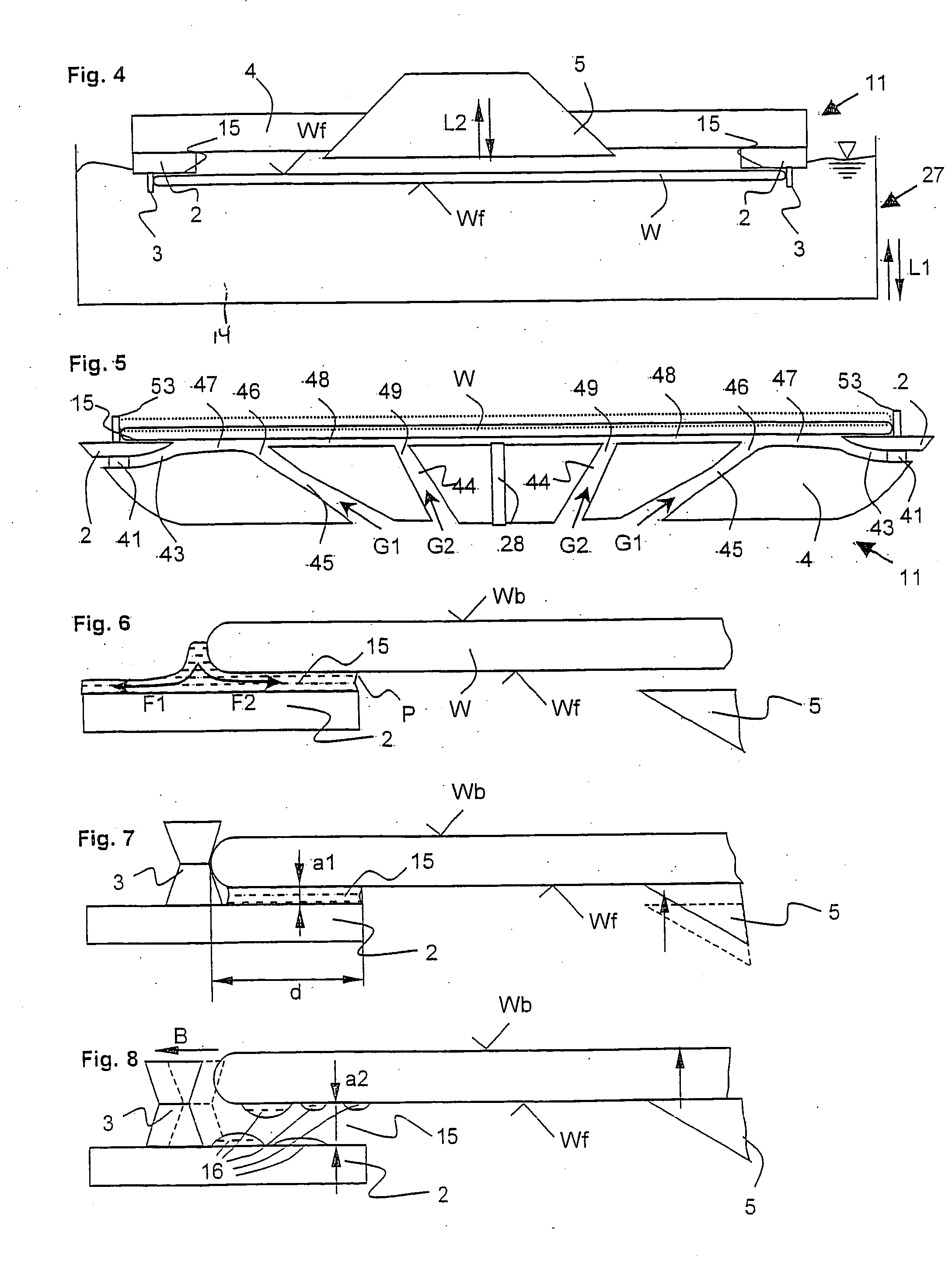
[0044]FIG. 4 shows a The device consists of a bath 14 in which the treatment liquid is located and which can be moved up and down (arrow L1), and of a carrier 11. The carrier 11 consists of a base body 4 and a ring 2 which is molded on underneath. Pins 3 with notches which are made underneath on the ring 2 hold the wafer W on the peripheral side, at a defined gap distance to the ring 2 so that the wafer in the horizontal position is suspended underneath on the carrier. The carrier 11 together with the wafer W is immersed into the bath tank 27 so far that the liquid level wets the ring 2 and thus the surface Wb of the wafer facing away from the ring and the peripheral-side wafer edge are completely wetted. The liquid penetrates into the gap between the wafer and ring. The carrier 11 is lifted out of the bath after treatment. A vacuum-pickup 5 which is mounted within the carrier is moved down so that it touches and suctions the wafer on the surface Wf of the wafer facing the mask. Af...


PUM


Abstract

A device for liquid treatment of a defined area of a wafer-shaped article, especially of a wafer, in which a mask is kept at a defined short distance to the wafer-shaped article such that liquid can be retained between the mask and the defined area of the wafer-shaped article by capillary forces.

Description

CROSS REFERENCE TO RELATED APPLICATIONS [0001] This application is a division of co-pending Application Ser. No. 09 / 984,707, filed on Oct. 31, 2001, the entire contents of which are hereby incorporated by reference.BACKGROUND OF THE INVENTION [0002] The invention relates to a device and a process for liquid treatment of a defined area of the main surface of a wafer-shaped article, especially a wafer. [0003] The reason for treatment of a defined section of a wafer-shaped article, i.e. the section near the edge, especially of a wafer, will be described below. [0004] A wafer, for example a silicon wafer, can have for example a coating of silicon dioxide on all sides. For subsequent processes (when for example a gold layer or a layer of polysilicon (polycrystalline silicon) is to be applied) it can be necessary to remove the existing coating from the wafer at least in the edge area of the main surface, but also optionally in the area of its peripheral surface and / or the second main surf...

Claims


Application Information

Patent Timeline
IPC IPC(8): H01L21/683H01L21/00H01L21/304H01L21/306
CPCH01L21/67075H01L21/6704H01L21/304
Inventor ENGESSER, PHILIPP
Owner LAM RES AG
Why Eureka
Try Eureka