Plug connector arrangement

a plug and connector technology, applied in the direction of coupling device connection, coupling parts engagement/disengagement, incorrect coupling prevention, etc., can solve the problems of electrical connection mechanical failure, electrical connection may be exposed to violent jolting and vibration force, and electrical connection may be subject to considerable mechanical load, so as to reduce rattling

Inactive Publication Date: 2005-02-03
TE CONNECTIVITY GERMANY GMBH
View PDF6 Cites 23 Cited by
  • Summary
  • Abstract
  • Description
  • Claims
  • Application Information

AI Technical Summary

Benefits of technology

[0003] The invention provides an electrical plug connector arrangement capable of taking up loads directed in the radial direction and reducing rattling caused by radial jolting and vibration forces. In an exemplary embodiment of the invention, an electrical plug connector arrangement has a plug or socket connector which is arranged in a housing and may be brought into an electrical contact with a mating connector by the actuation of an actuation lever arranged movably on the connector. This actuation lever is movable between a free position in which the two connectors are not in an electrical contact (unmated) and a coupled position in which the two connectors are in an electrical contact (mated). The actuation lever has a clamping projection extending therefrom between the connector and the housing. When the actuation lever is in the coupled position, the clamping projection is in engagement with a mating clamping projection on the housing, opposite the clamping projection on the lever.

Problems solved by technology

These connections, however, may be exposed to violent-jolting and vibration forces.
These jolting and vibration forces result in considerable mechanical loads, in particular on the cables leading from the plug connector arrangement and the electrical contacts connected to these cables and involved in the plug connection.
These forces occur, both in the mating direction (i.e., axial to the connectors) and transversely with respect to the mating direction (i.e., the radial direction), and may cause mechanical failures in the electrical connections.
Also, these jolting and vibration forces can cause undesirable rattling.

Method used


Image

  • Plug connector arrangement
  • Plug connector arrangement
  • Plug connector arrangement

Examples


Embodiment Construction

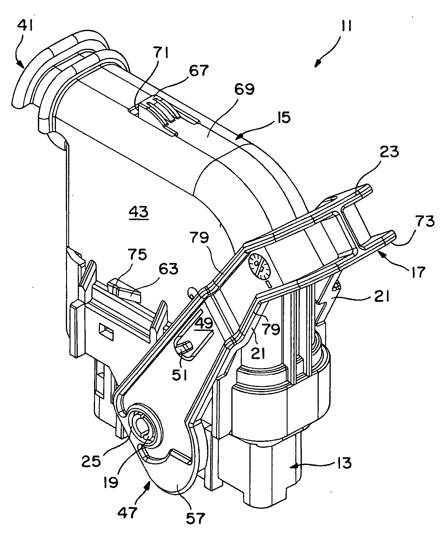
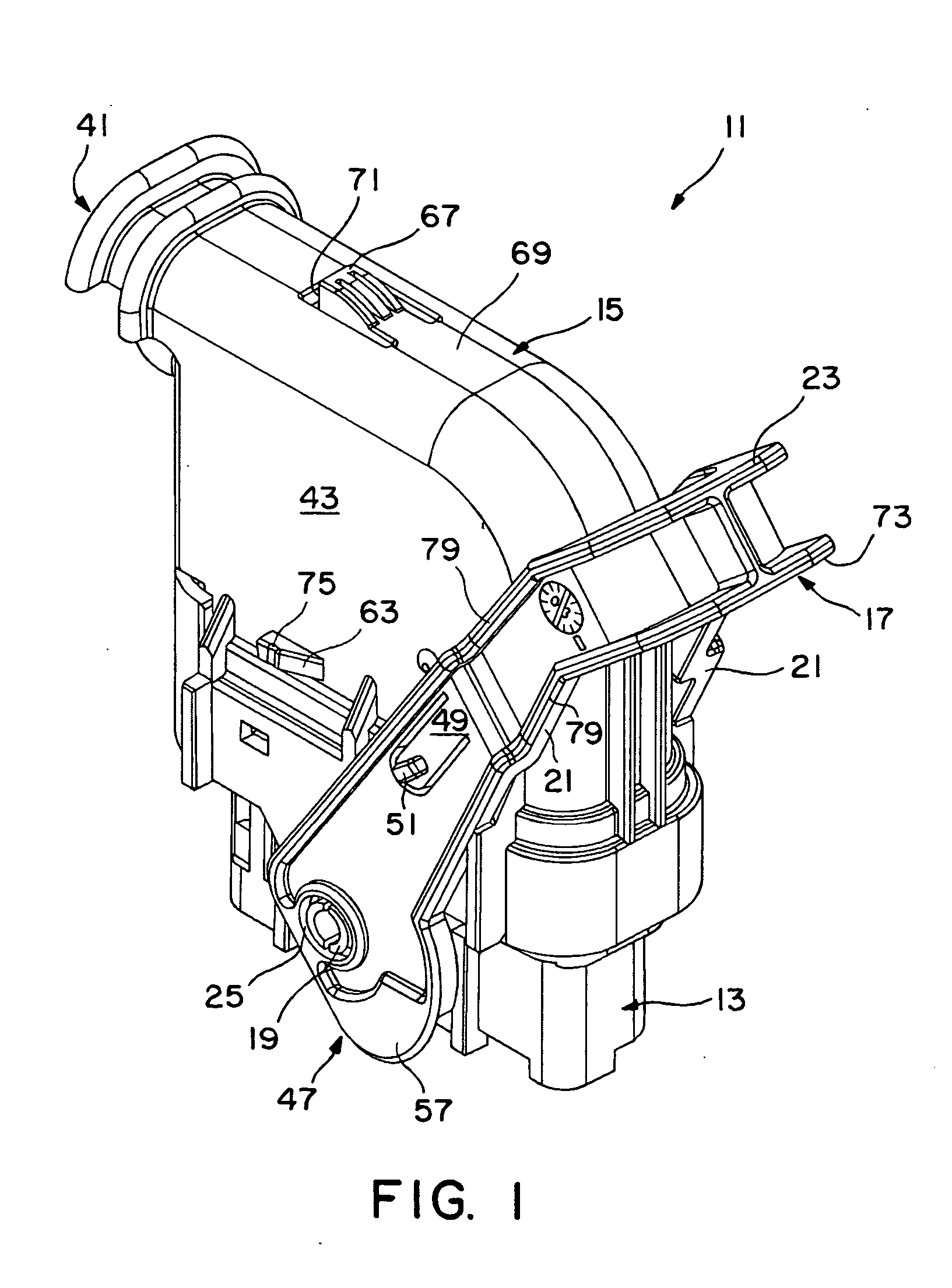
[0015]FIG. 1 shows a perspective illustration of an electrical connector arrangement 11 according to an exemplary embodiment of the invention, having a socket connector 13. The socket connector has contacts (not shown) at one end (the bottom in FIG. 1) and a cable extending from the other end (not visible in FIG. 1). The cable end of the socket connector 13 is covered by a connector cover 15. An actuation lever 17 is articulated to the connector cover 15 such that it can pivot by means of pivot pegs 19 (of which only one is visible in FIG. 1). The actuation lever 17 is a two-armed pivotal lever that is substantially U-shaped. To this end, each of two lever arms 21, together with a handle 23 having a stirrup shape, form the U-shaped actuation lever 17. The lever arms 21 are each provided with a pivot peg receiving opening 25 at a free end 47 of the lever arm 21 remote from the handle 23.

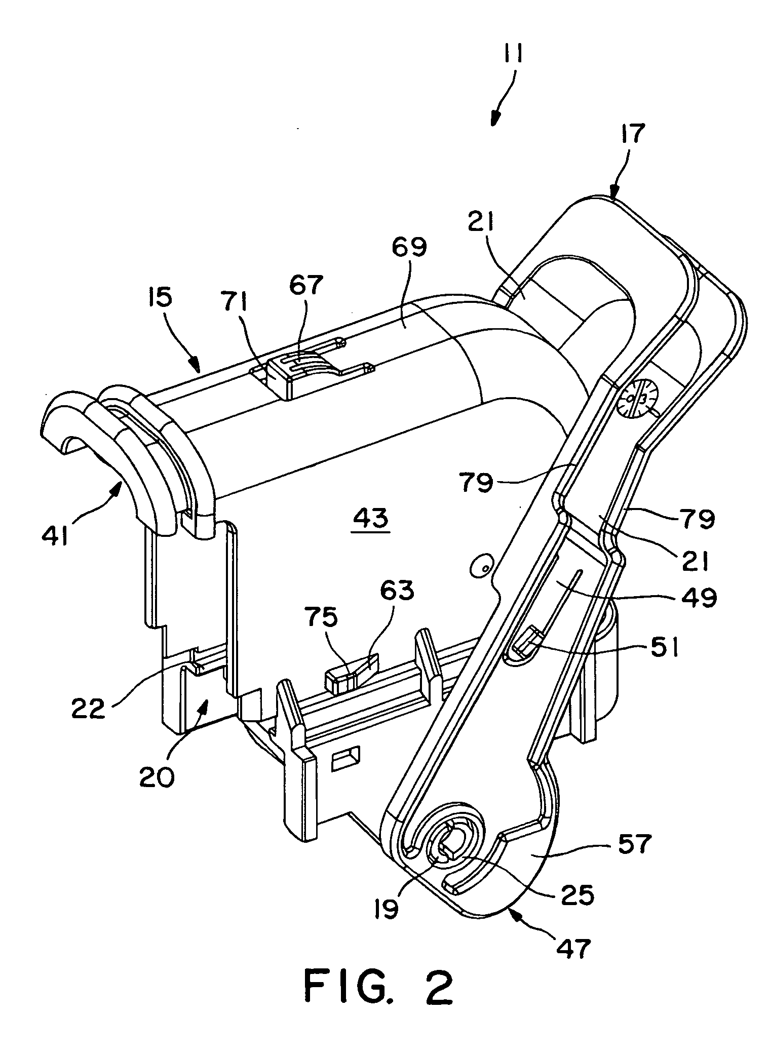
[0016] FIGS. 2 to 4 show only the connector cover 15 and the pivotal actuation lever 17. A receiv...


PUM


Abstract

An electrical connector arrangement having a first connector which is arranged in a housing and may be brought into an electrical connection with a mating connector by the actuation of an actuation lever arranged movably on the first connector. The actuation lever being movable between a free position in which the two connectors are not fully mated and a coupled position in which the two connectors are fully mated. A portion of the actuation lever is disposed between the first connector and the housing with a clamping projection on the lever that is in engagement with a mating clamping projection on the housing when the actuation lever is in the coupled position.

Description

FIELD OF THE INVENTION [0001] The invention relates to an electrical plug connector arrangement having a connector arranged in a housing and an actuation lever movably arranged on the connector or the housing to bring the connector into mating connection with a mating connector by the actuation of the actuation lever. BACKGROUND OF THE INVENTION [0002] Plug connector arrangements are used in many locations within an automobile to make electrical connections. For example, in the engine compartment or on a gear of a motor vehicle electrical connections are typically needed. These connections, however, may be exposed to violent-jolting and vibration forces. These jolting and vibration forces result in considerable mechanical loads, in particular on the cables leading from the plug connector arrangement and the electrical contacts connected to these cables and involved in the plug connection. These forces occur, both in the mating direction (i.e., axial to the connectors) and transverse...

Claims


Application Information

Patent Timeline
Patent Type & Authority Applications(United States)
IPC IPC(8): H01R13/533H01R13/629
CPCH01R13/533H01R2201/26H01R13/6295H01R13/62944
Inventor DEMUTH, ULRICH
Owner TE CONNECTIVITY GERMANY GMBH
Why Eureka
Try Eureka