Portable electrocardiograph

a portable electrocardiograph technology, applied in the field of portable electrocardiographs, can solve the problems of inability to accurately diagnose patients, disturbance of measured electrocardiographic waveforms, and inability to measure precision,

Active Publication Date: 2005-02-03
OMRON HEALTHCARE CO LTD
View PDF11 Cites 28 Cited by
  • Summary
  • Abstract
  • Description
  • Claims
  • Application Information

AI Technical Summary

Benefits of technology

[0022] An object of the present invention is to provide a portable electrocardiograph which consistently enables stable contact between an electrode and the human body.

Problems solved by technology

However, stationary electrocardiographs suffer from the fact that, in many cases, the events they are seeking to monitor have past and therefore a proper diagnosis is not possible.
However, since this method requires that the electrodes remain attached for a period of days, patients are greatly inconvenienced and subject to a great deal of pain and discomfort.
In the case where stable contact is not maintained, the measured electrocardiographic waveforms are disturbed and cannot be measured with precision.
Consequently, the measurement circuit does not cross the heart, so that electrocardiographic waveforms cannot be measured with precision.
In such a state, it is difficult to detect ischemic cardiomyopathies of an early stage and the object itself of measuring electrocardiographic waveforms may be lost.
However, if the wrist is not fixed by pressing the right hand against the right side of the body, the contact between the electrode and the body becomes unstable and a large disturbance occurs in the measured electrocardiographic waveforms.
In such a state, it is very difficult to stably maintain the contact between the electrode and the body and the body moves inevitably at the time of measurement.

Method used


Image

  • Portable electrocardiograph
  • Portable electrocardiograph
  • Portable electrocardiograph

Examples


first embodiment

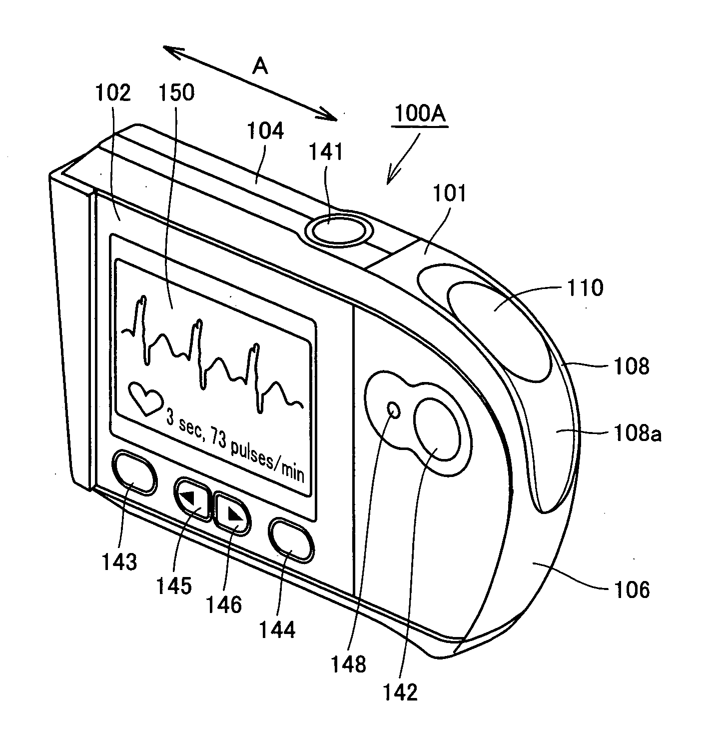
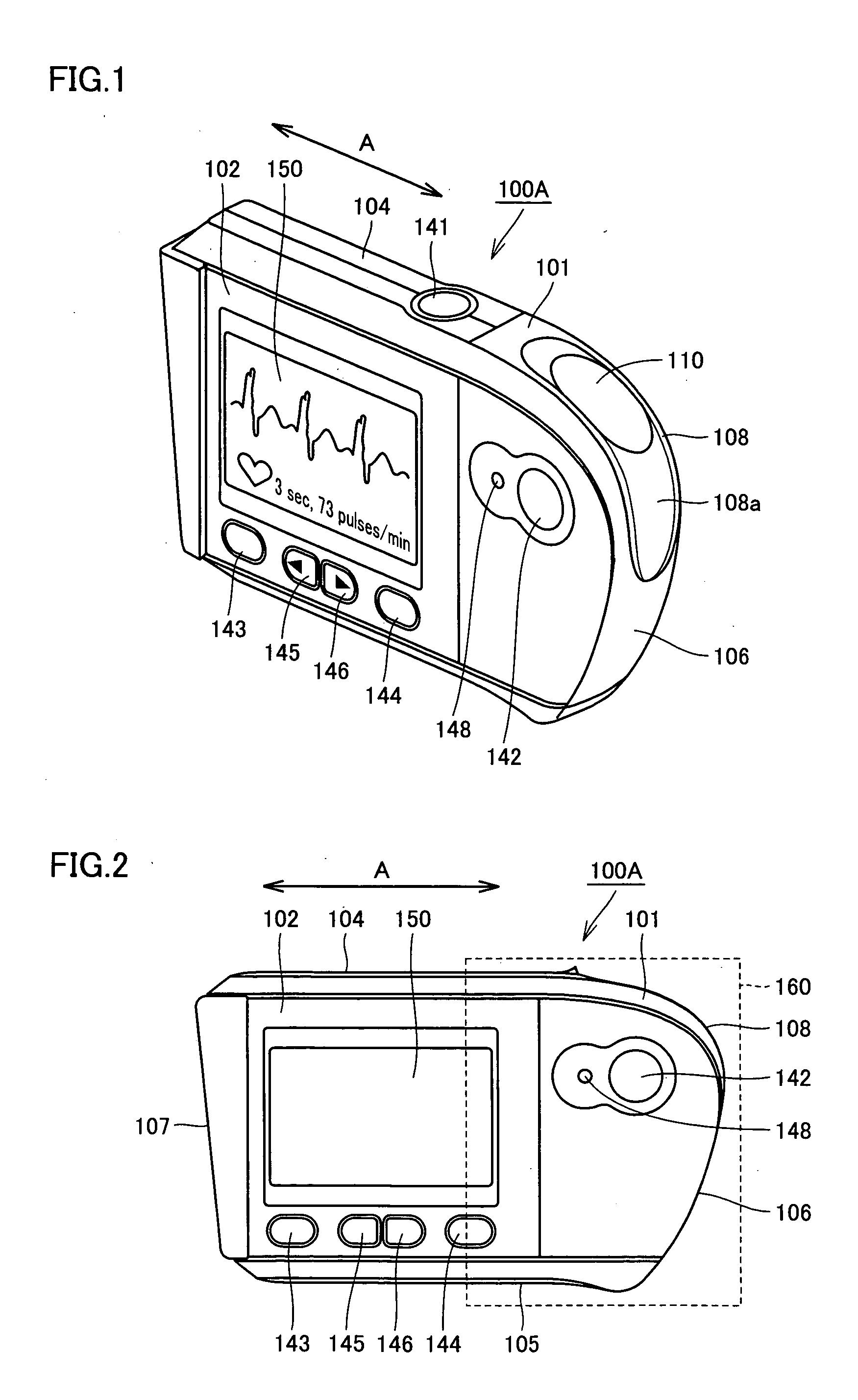
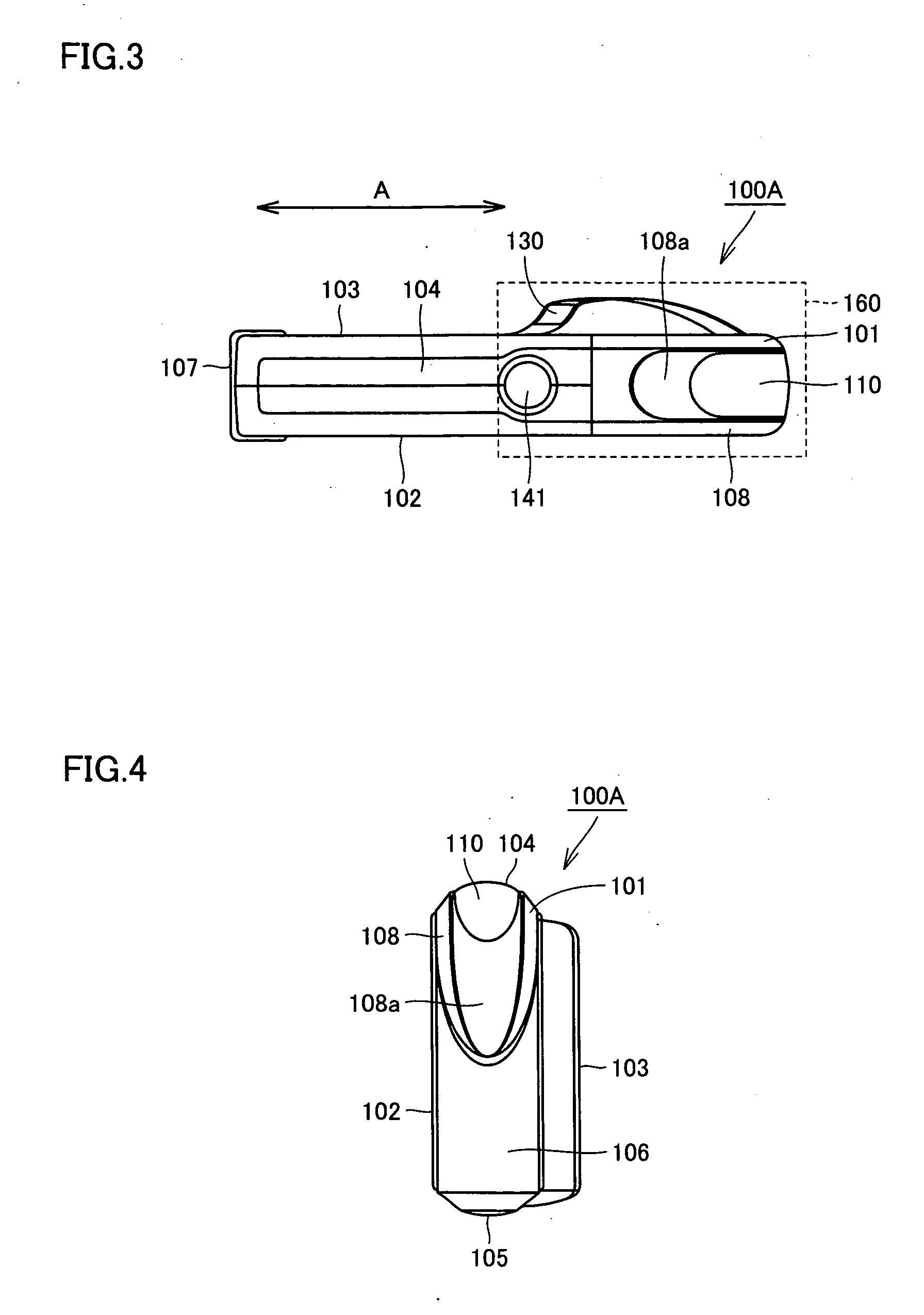
[0066] First, the structure of a portable electrocardiograph 100A in the first embodiment will be described. As shown in FIGS. 1 to 6, the portable electrocardiograph 100A in this embodiment is formed light and small so as to be easily handled and can be held by one hand. The portable electrocardiograph 100A has a housing 101 of a flat and elongated almost rectangular parallelepiped shape. On the outer surfaces (front face 102, rear face 103, top face 104, bottom face 105, right side face 106, left side face 107 and curved face 108), a display unit, an operation unit, electrodes and the like are arranged.

[0067] As shown in FIGS. 1 and 2, a grip part 160 as a grip region is provided adjacent to an end in the longitudinal direction (the direction of the arrow A in the figure) of the housing 101. The grip part 160 is a portion provided so that the test subject can stably hold the main body of the portable electrocardiograph 100A at the time of measurement. At the time of measurement, ...

second embodiment

[0099] First, the structure of a portable electrocardiograph 100B in a second embodiment will be described. The same reference numerals will be given to components similar to those in the foregoing first embodiment and their description will not be repeated here.

[0100] As shown in FIGS. 16 and 17, the portable electrocardiograph 100B in this embodiment is different from the portable electrocardiograph 100A in the first embodiment only with respect to the structure of the left side face 107 as the electrode formation face of the housing 101.

[0101] The portable electrocardiograph 100B in this embodiment has the positive electrode 120 as the second electrode on the left side face 107 of the housing 101. The positive electrode 120 is made of an electroconductive material and is positioned at the center portion of the left side face 107 of the housing 101. Around the positive electrode 120, the flat face 107a made of an insulating material is formed. The contact face 121 with the body ...

third embodiment

[0107] First, the structure of a portable electrocardiograph 100C in a third embodiment will be described. The same reference numerals will be given to components similar to those in the foregoing first embodiment and their description will not be repeated here.

[0108] As shown in FIGS. 18 and 19, the portable electrocardiograph 100C in this embodiment is different from the portable electrocardiograph 100A in the first embodiment only with respect to the structure of the left side face 107 as the electrode formation face of the housing 101.

[0109] The portable electrocardiograph 100C in this embodiment has the positive electrode 120 as the second electrode on the left side face 107 of the housing 101. The positive electrode 120 is made of an electroconductive material and is positioned at the center portion of the left side face 107 of the housing 101. Around the positive electrode 120, the flat face 107a made of an insulating material is formed. The contact face 121 with the body a...


PUM


Abstract

A portable electrocardiograph and method of use are disclosed. According to one aspect of the present invention, a portable electrocardiograph is provided which includes: a rectangular housing having at least a first outer surface and a second outer surface; a first electrode provided on the first outer surface of the housing; an electrode formation face provided on the second outer surface of the housing; and a second electrode provided within the electrode formation face; wherein the electrode formation face includes an electrode region in which the second electrode is positioned and a non-electrode region which is positioned so as to surround the electrode region.

Description

BACKGROUND OF THE INVENTION [0001] 1. Field of the Invention [0002] The present invention relates to a portable electrocardiograph capable of easily measuring and storing electrocardiographic waveforms. [0003] 2. Description of the Background Art [0004] Generally, for diagnosing ischemic cardiomyopathies such as angina pectoris and myocardial infarction, an electrocardiograph of the patient is used. Known electrocardiographs for measuring electrocardiographic waveforms include stationary electrocardiographs and portable electrocardiographs. [0005] Stationary electrocardiographs are generally found in medical institutions such as hospitals, and they measure waveforms by attaching electrodes to the body of a patient who lies on a bed or the like. The use of a stationary electrocardiograph is advantageous because it is able to measure various electrocardiographic waveforms (such as P waveform and QRS waveform) very precisely. However, stationary electrocardiographs suffer from the fact...

Claims


Application Information

Patent Timeline
Patent Type & Authority Applications(United States)
IPC IPC(8): A61B5/332
CPCA61B2560/0468A61B5/0404A61B5/332
Inventor UMEDA, MASAHIROYAMAMOTO, NORIHITOTANABE, KAZUHISAISHIDA, JUNICHIMOROKI, YOKO
Owner OMRON HEALTHCARE CO LTD
Why Eureka
Try Eureka