Vegetable retainer for vegetable cooking utensil

a vegetable and retainer technology, applied in the field of vegetable retainer for vegetable cooking utensils, can solve the problems of coming into contact with the flat blade and the comb blade, and achieve the effect of efficiently draining

Inactive Publication Date: 2005-02-10
BENRINER
View PDF5 Cites 35 Cited by
  • Summary
  • Abstract
  • Description
  • Claims
  • Application Information

AI Technical Summary

Benefits of technology

[0021] According to the invention as described in claim 2, additionally to the effect of the invention as described in claim 1, the vegetable retainer can be held further reliably, a finger of a cooking person is in contact with the inner surface of the rising portion which extends upwardly extending in a direction along the front and rear ends of the vegetable retainer or it is placed on an inner side thereof so that the finger is prevented from projecting, whereby safety performance can be improved, and drainage of water remaining on the vegetable retainer can be performed by means of the notch.
[0022] Further, the invention as described in claim 3 is the vegetable retainer for a vegetable cooking utensil as set forth in claim 1 or 2, wherein the notch is formed at respective two positions on the rising portion near front and rear ends.
[0023] According to the invention as described in claim 3, additionally to the effects of the invention as described in claim 1 or 2, water remaining on the vegetable retainer can be drained efficiently from the notches formed at respective two positions on the rising portion.

Problems solved by technology

In that case, there is the danger that they come into contact with the flat blade and the comb blade 4 and are injured.

Method used


Image

  • Vegetable retainer for vegetable cooking utensil
  • Vegetable retainer for vegetable cooking utensil
  • Vegetable retainer for vegetable cooking utensil

Examples


Embodiment Construction

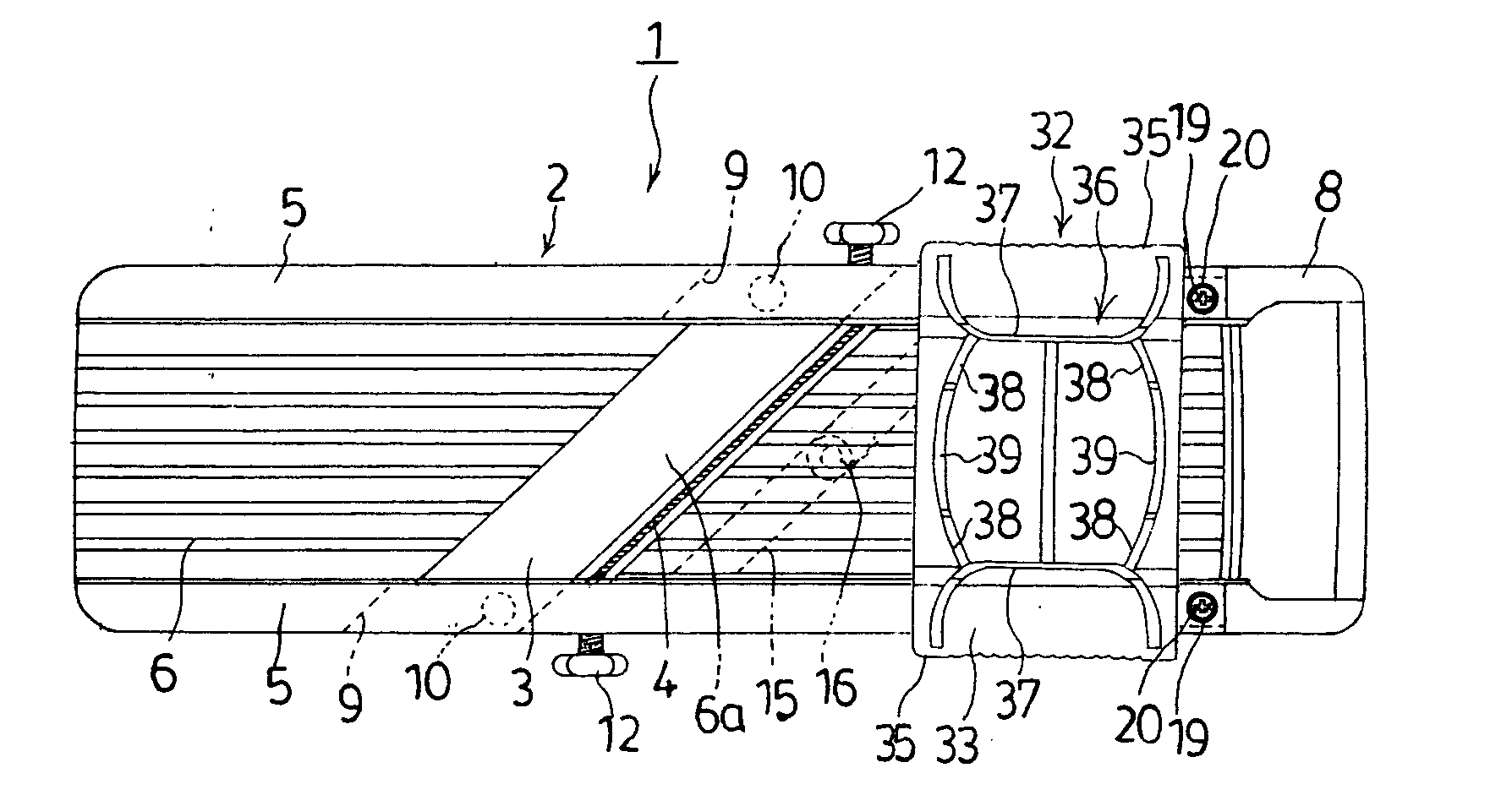
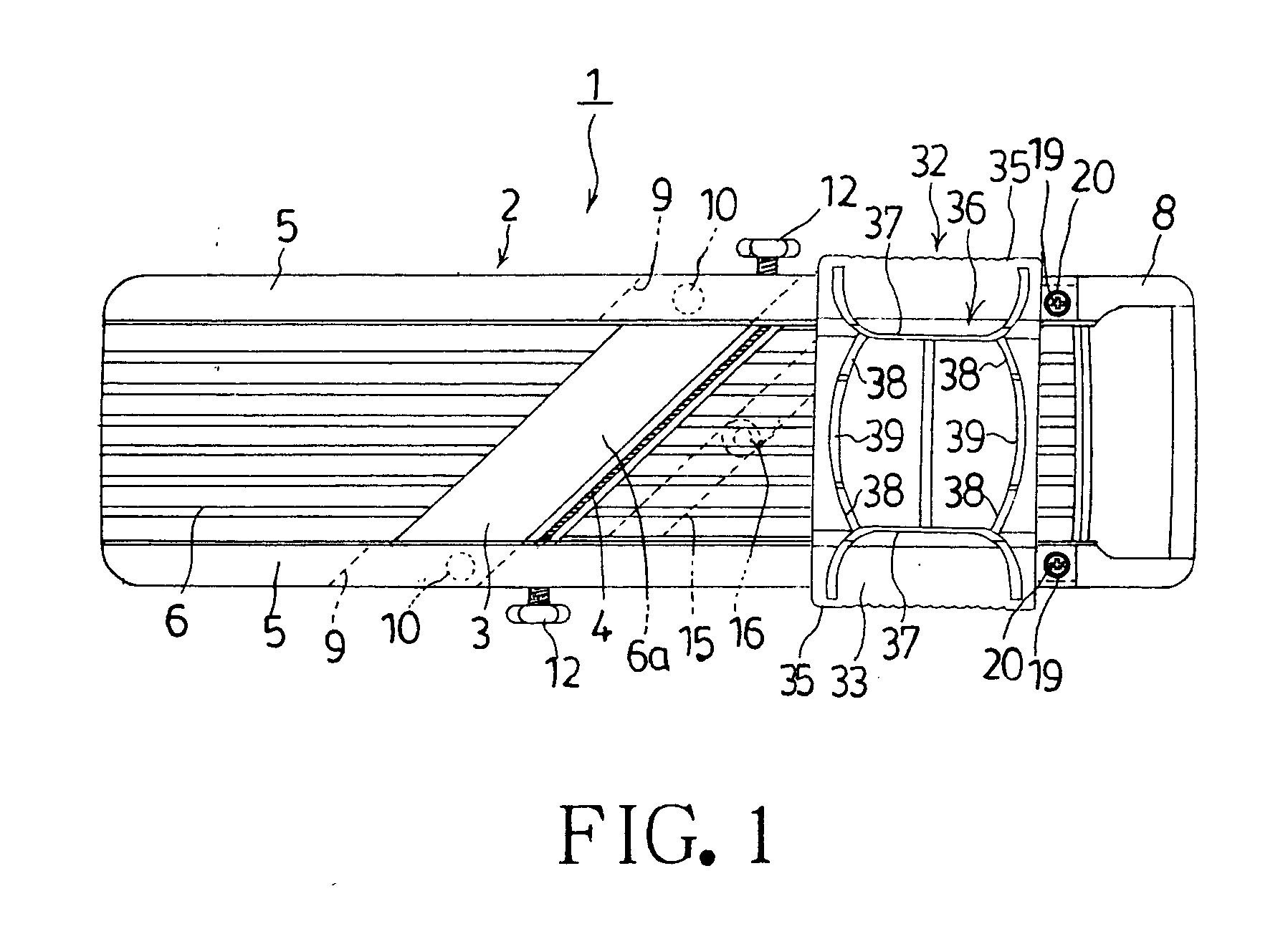
[0040] One embodiment of the present invention will be explained in detail below according to FIGS. 1 to 5. Like reference numerals are assigned to the same constructive portions as those of the prior art example, and explanation thereof will be omitted for convenience of explanation. In FIG. 1, the reference numeral 32 denotes a vegetable retainer employed instead of the vegetable retainer (21 in FIG. 11) of the prior art example. As shown in FIG. 2 and FIG. 3, this vegetable retainer 32 consists of a flat plate-like retainer main body portion 33 whose central portion underside is recessed forming a level difference to form a recess 33a, a vegetable retaining portion 34 which protrudes from the recess 33a and which is constructed of a plurality of comb teeth bodies 34a, 34a, . . . for being stuck into a vegetable to retain the vegetable, sliding portions 35, 35 which extend vertically on both side portions of the retainer main body portion 33 and which are guided by the left and ri...


PUM


Abstract

In a vegetable retainer employed for a vegetable cooling utensil which is provided with a flat blade and a comb blade on a roughly central portion in a longitudinal direction of a vegetable cooking utensil main body of a roughly rectangle in a plan view to shred a vegetable and the like, in order that the vegetable retainer can be held reliably and that a finger tip is prevented from coming into contact with a cooking blade so that safety performance is improved, the vegetable retainer comprises an approximately flat plate-like retainer main body portion whose central portion underside is recessed to form a recess, a vegetable retaining portion which protrudes from the recess and which is constructed of a plurality of comb teeth bodies for being stuck into a vegetable and the like to retain it, sliding portions which extend vertically on both side portions of the retainer main body portion and which are guided by both side portions of the vegetable cooking utensil main body to slide, and a holding portion which extends upwardly from an upper surface of the retainer main body portion and by which a cooking person holds the vegetable retainer.

Description

BACKGROUND OF THE INVENTION [0001] 1. Field of the Invention [0002] The present invention relates to a vegetable retainer for a vegetable cooking utensil and in particular to a vegetable retainer for a vegetable cooking utensil in which holding a vegetable holder can be performed reliably and safety performance is improved by preventing a finger tip from projecting and from coming into contact with a cooking blade in a vegetable retainer employed for a vegetable cooking utensil constructed by comprising a flat blade and a comb blade so as to shred vegetables and the like. [0003] 2. Description of the Prior Art [0004] This conventional type of vegetable cooking utensil will be explained according to FIGS. 5 to 14. The present applicant has already filed a patent application regarding this conventional type of vegetable cooking utensil (refer to Patent Document 1), and this vegetable cooking utensil will be explained according to FIGS. 5 to 10. In FIG. 5, the reference numeral 1 denot...

Claims


Application Information

Patent Timeline
Patent Type & Authority Applications(United States)
IPC IPC(8): A47J43/25A47J43/28B26D3/28
CPCA47J43/25B26D2003/287B26D3/283
Inventor YAMAMOTO, HAJIME
Owner BENRINER
Why Eureka
Try Eureka