Connector

a technology of connecting rods and connectors, applied in the direction of coupling device connection, coupling protective earth/shielding arrangement, securing/insulating coupling contact members, etc., to achieve the effect of preventing relative displacement, preventing projection, and preventing abrasion

Active Publication Date: 2006-09-12
SUMITOMO WIRING SYST LTD
View PDF6 Cites 27 Cited by
  • Summary
  • Abstract
  • Description
  • Claims
  • Application Information

AI Technical Summary

Benefits of technology

[0007]The invention relates to a connector with first and second housings. The first housing accommodates at least one first terminal fitting and has a receptacle for surrounding parts of the first terminal fittings. The second housing accommodates at least one second terminal fitting. The first and second terminal fittings are connectable by fitting the second housing into the receptacle. The second housing includes a substantially tubular fitting that fits to the receptacle. At least one preventing projection is provided on at least one of the receptacle and the tubular fitting in a position to contact the mating side near the end of the connection of the first and second housings. For example, preventing projections may be at the leading end of the receptacle and / or the back end of the tubular fitting. The preventing projection prevents relative displacement of the receptacle and the tubular fitting, and thus prevents abrasion between the terminal fittings due to fine sliding movements.
[0011]The preventing projections preferably are disposed to avoid creating significant connection resistance until a stage immediately before the proper connection of the two housings. Thus, connection efficiency is good.
[0016]The presence of the lock arm and the lock on the upper walls of tubular fitting and the receptacle may complicate the disposition of the preventing projections on the upper walls. However, a vertical displacement of the housings is prevented by the left and right preventing projections on the guiding ribs or the guiding grooves and the preventing projections on the bottom walls of the receptacle or the tubular fitting.
[0018]At least one notch may be provided on a part of the tubular fitting that has the preventing projection. The notch makes adjacent parts of the tubular fitting resiliently displaceable. The preventing projection contacts the receptacle in the process of connecting the housings, and is displaced away from the receptacle. Thus, the connection resistance resulting from the interference of the preventing projection and the receptacle is reduced.
[0019]An area of the outer surface of the tubular fitting between a pair of notches is recessed to form a thinned portion. Thus, the area of the tubular fitting where the preventing projection is formed is thinned to displace more easily, and the female housing is made lighter.

Problems solved by technology

Thus, the connected housings shake slightly, and this shaking leads to abrasion caused by fine sliding movements between the terminal fittings.

Method used


Image

  • Connector
  • Connector
  • Connector

Examples


Embodiment Construction

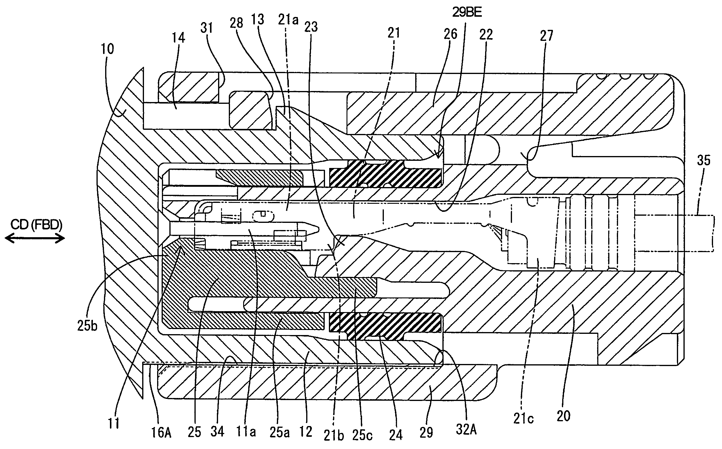
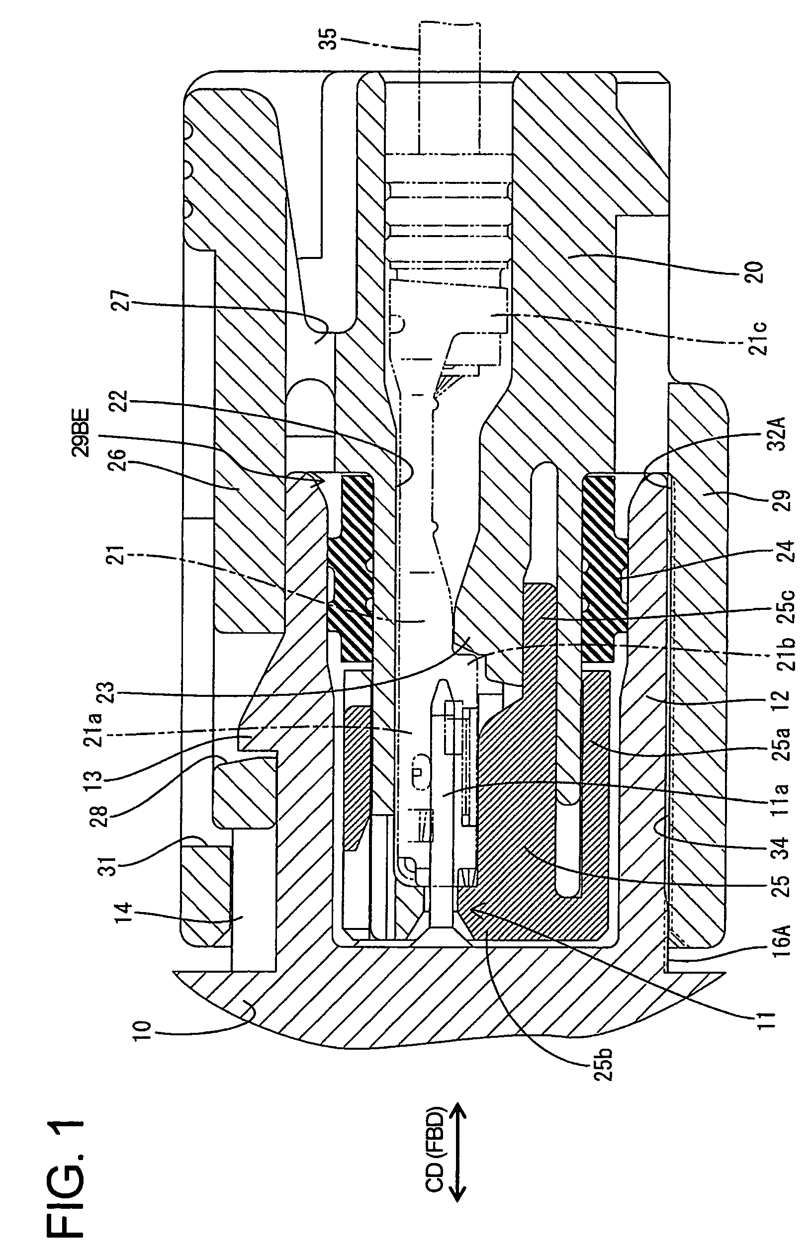
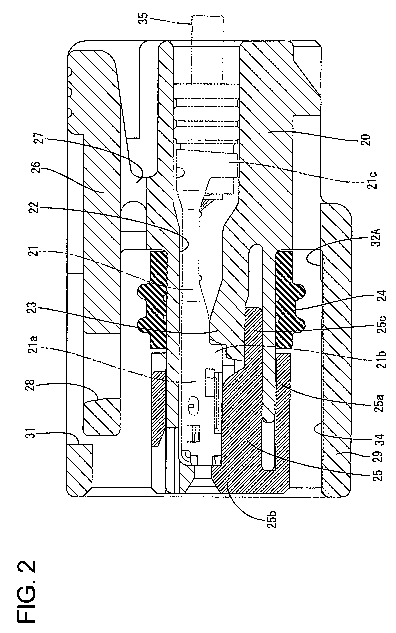
[0038]A connector according to a first embodiment of the invention is described with reference to FIGS. 1 to 12. The connector of this embodiment has a male housing 10 accommodating male terminal fittings 11 and a female housing 20 accommodating female terminal fittings 21. Connecting sides of each housing 10, 20 are referred to herein as the front.

[0039]The male housing 10 is made e.g. of a synthetic resin and has a receptacle 12 that projects forward in substantially the same direction as a connecting direction CD with the female housing 20. Long narrow tabs 11a project forward on the male terminal fittings 11 into the receptacle 12. Thus, the receptacle 12 protects the tabs 11a from interference by external matter. A lock 13 projects up on the outer surface of the upper wall of the receptacle 12 at a substantially middle position with respect to the width direction WD and forward and backward directions FBD of the receptacle 12. Rib-shaped projections 14 are formed on the outer s...


PUM


Abstract

A male housing (10) includes male terminal fittings (11), and a receptacle (12) for surrounding tabs (11a) of the male terminal fittings (11). A female housing (20) includes female terminal fittings (21) and a tubular fitting (29) fittable on the receptacle (12). Since preventing projections (32A, 32B, 32C) for preventing relative displacements of the receptacle (12) and the tubular fitting (29) by contacting the outer surface of the receptacle (12) are provided at the back end of the inner surface of the tubular fitting (29), an abrasion between the terminal fittings (11, 21) due to fine sliding movements resulting from the relative displacements of the two housings (10, 20) can be prevented.

Description

BACKGROUND OF THE INVENTION[0001]1. Field of the Invention[0002]The present invention relates to a connector.[0003]2. Description of the Related Art[0004]U.S. Pat. No. 5,336,540 discloses a connector with male and female housings. The male housing has a receptacle that surrounds tabs of male terminal fittings. The female housing has female terminal fittings that connect with the tabs by fitting the female housing into the receptacle of the male housing.[0005]A clearance is defined between the outer surface of the female housing and the inner surface of the receptacle due to dimensional and assembling tolerances. Thus, the connected housings shake slightly, and this shaking leads to abrasion caused by fine sliding movements between the terminal fittings. As a result, there is a demand to eliminate the shaking[0006]The invention was developed in view of the above problem and an object thereof is to prevent an abrasion caused by fine sliding movements between terminal fittings.SUMMARY ...

Claims


Application Information

Patent Timeline
Patent Type & Authority Patents(United States)
IPC IPC(8): H01R4/38
CPCH01R13/5221H01R13/4364H01R13/56
Inventor FUKATSU, YUKIHIROTOYODA, YUKIHIROICHIDA, KIYOFUMI
Owner SUMITOMO WIRING SYST LTD
Why Eureka
Try Eureka