Tool case

a tool and case technology, applied in the field of tool cases, can solve the problems that the socket of a ratchet wrench is especially difficult to remove from the cavity of a tool with a smooth outer surface, and achieve the effect of convenient and convenient removal

Inactive Publication Date: 2005-02-10
CHEN KUN CHEN
View PDF13 Cites 21 Cited by
  • Summary
  • Abstract
  • Description
  • Claims
  • Application Information

AI Technical Summary

Benefits of technology

[0008] The main objective of the invention is to provide a tool case from which tools can be removed conveniently from cavities in the tool case in which the tools are stored. The tool case has a body, at least one baffle and a positioning device. The body has a recess with a bottom and multiple cavities defined in the bottom of the recess for storing tools. The at least one baffle is pivotally attached to the body with a pivot pin, is mounted in the recess and corresponds to the cavities in the body. The positioning device is mounted in the inner surface of the cavity for positioning the at least one baffle relative to the body. Accordingly, the tools can be kept from escaping from the cavities with a blocking effect provided by the at least one baffle plate a positioning device does not need to be formed in each respective cavity. Therefore, the tools can be easily and conveniently removed from the corresponding cavities.

Problems solved by technology

However, removing the tool from the cavity with a conventional positioning device requires a large force to push away the protrusions, and that is difficult. a tool with a smooth outer surface such as a socket for a ratchet wrench is especially difficult to remove from a cavity.

Method used


Image

  • Tool case
  • Tool case
  • Tool case

Examples


first embodiment

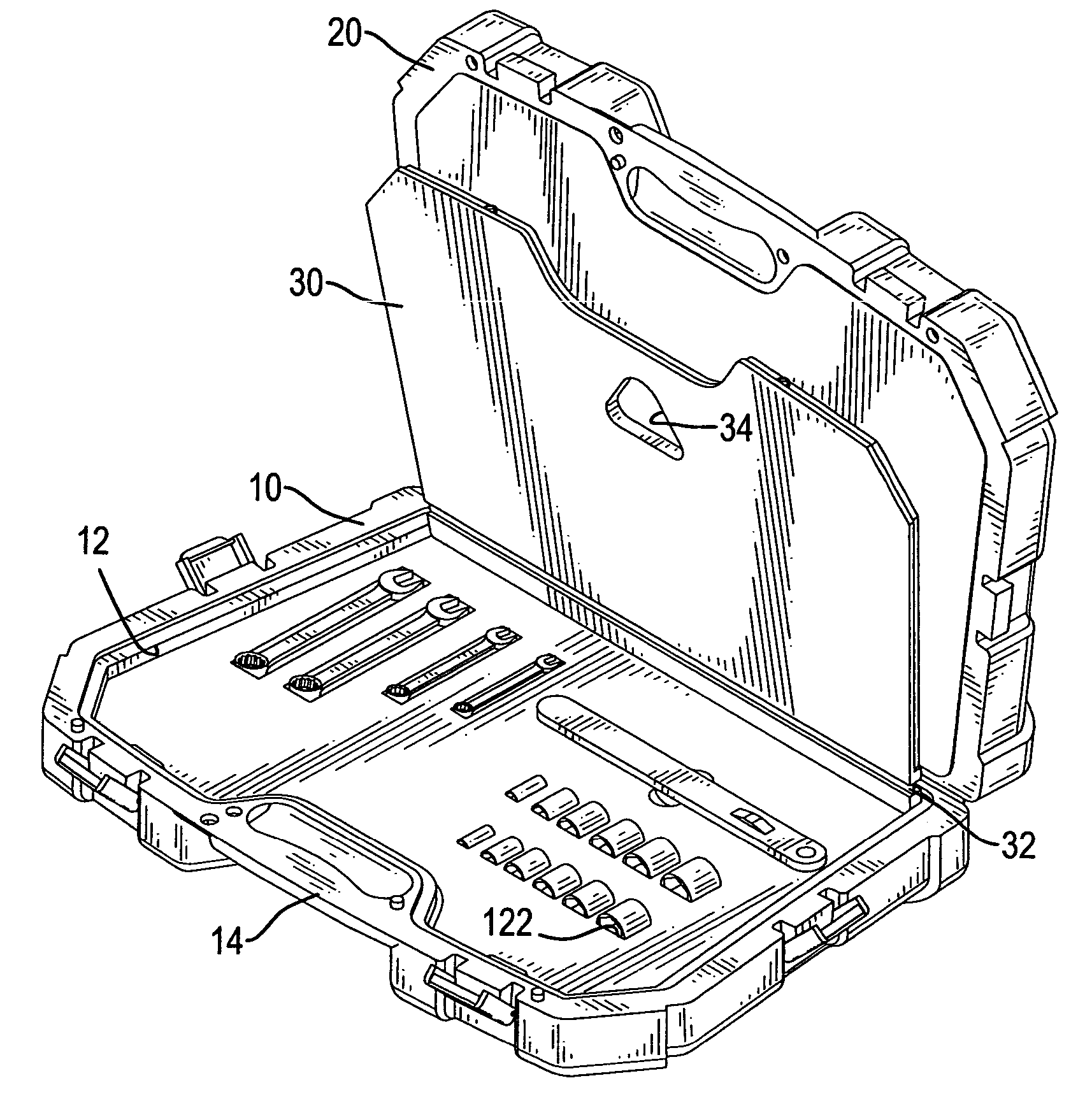
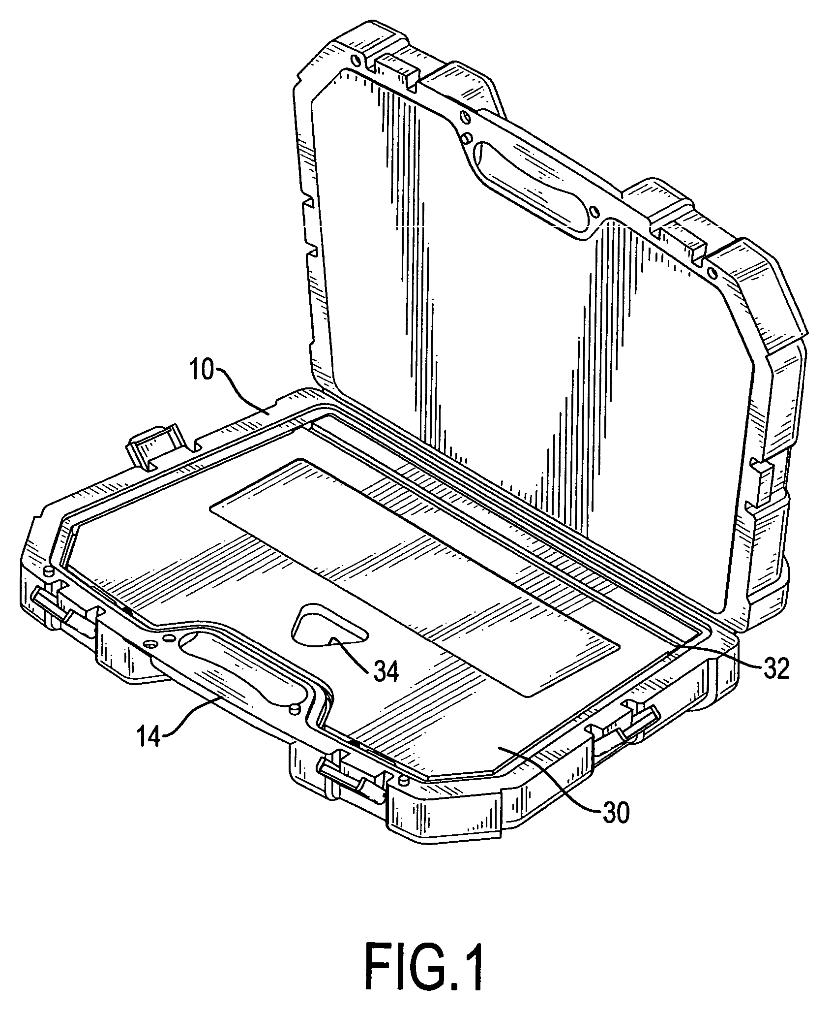
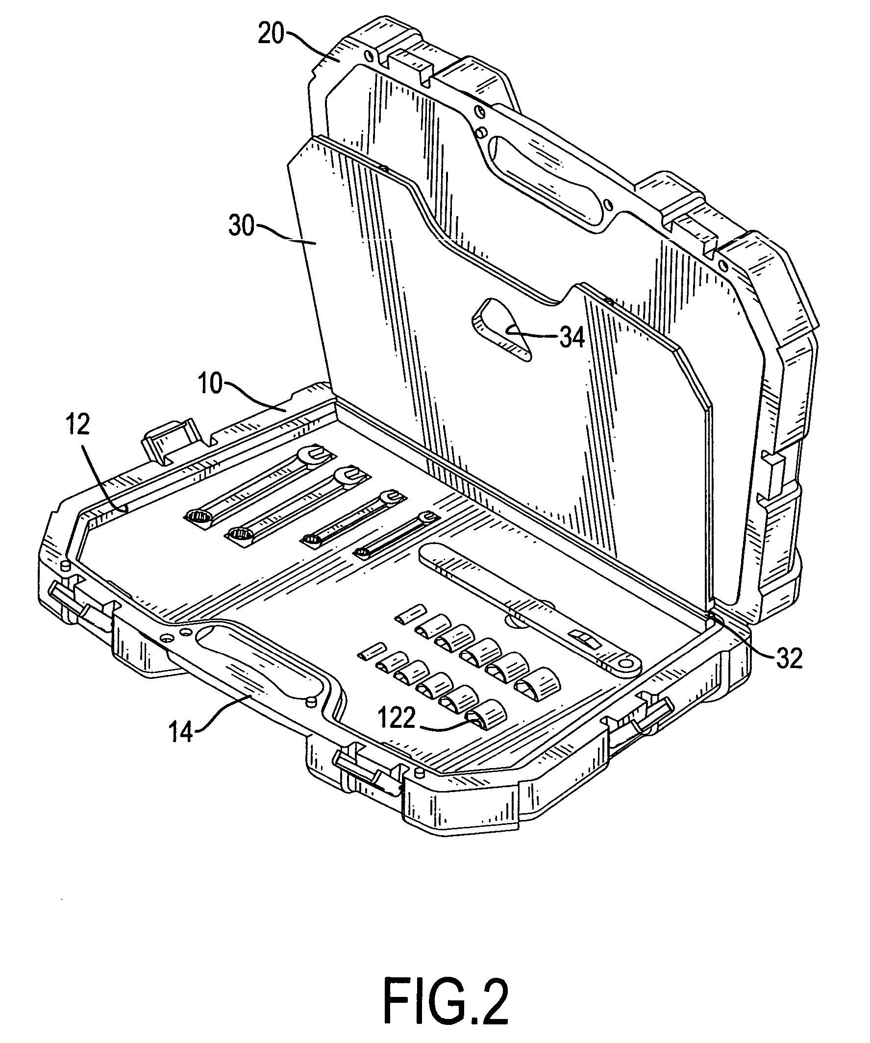
[0016] With reference to FIGS. 1 to 3, a tool case in accordance with the present invention comprises a body (10), a cover (20), a first baffle (30), a positioning device (not numbered). The body (10) has a top (not numbered), a recess (12), multiple cavities (122) and a handle (14). The recess (12) is defined in the top and has an inner surface (not numbered) and a bottom (not numbered). The cavities (122) are defined in the bottom of the recess (12) to hold tools (not numbered). the handle (14) is formed on the body (10) for a user to conveniently carry the tool case. The cover (20) is pivotally attached to the body (10).

[0017] The first baffle (30) is pivotally attached to the body (10) with a pivot pin (not numbered) and is selectively received in the recess (12). The first baffle (30) covers the cavities (122) in the body (10), has a board (not numbered), a resilient connector (32) and a hole (34). The board has edges (not numbered) and a thickness and is pivotally attached to ...

second embodiment

[0020] With reference to FIG. 4, the tool case in accordance with the present invention has a cover (20′) with a top (not numbered), a recess (not numbered), multiple cavities (not shown) and a handle (not numbered). The recess has a bottom and is defined in the top of the cover (20′). The multiple cavities (not shown) defined in the bottom of the recess to hold tools. The handle is formed on the cover and corresponds to the handle formed on the body. The cover is pivotally attached to the body at an edge away from the handle.

[0021] A second baffle (40) is pivotally attached to the cover (20′) with a pivot pin and is selectively received in the recess in the cover (20′). The second baffle (40) corresponds to the cavities in the cover (20′) to hold the tools in the cavities. The second baffle (40) has a structure the same as the first baffle (30) on the body (10) and comprises a board (not numbered), a resilient connector (not numbered) and a hole (not numbered). A second positioning...

third embodiment

[0022] With reference to FIG. 5, the tool case in accordance with the present invention has two body baffle (30′) pivotally attached to the body (10) and corresponding respectively to two groups of cavities (122) in the body (10). The body baffles (30′) may be made optionally of a transparent material. Accordingly, a person can see the tools stored in the cavities (122) through the body baffled (30′) and open the appropriate body baffle (30′) to retrieve a desired tool.

[0023] In an alternative embodiment of the tool case in accordance with the present invention, two cover baffles (not shown) can be mounted on the cover (20) when cavities (not shown) are defined in the cover (20) for storing tools.

[0024] With reference to FIG. 6, because the baffle (30″) can be held in position relative to the body (10′) to hold the tools in the cavities, the baffle (30″) can serve as a cover. Therefore, attaching a cover (20) to the body (10) as described in the first embodiment of the tool case is...


PUM


Abstract

A tool case has a body, at least one baffle and a positioning device. The body has a recess with a bottom and multiple cavities defined in the bottom of the recess to hold tools. The at least one baffle is pivotally attached to the body with a pivot pin, is selectively received in the recess and covers the cavities in the body. The positioning device is mounted in the inner surface of the cavity to hold the at least one baffle closed relative to the body. Accordingly, the tools can be held in the cavities by the at least one baffle, and forming a positioning device in each cavity is unnecessary. Consequently, removing the tools from the cavities is easy and convenient.

Description

BACKGROUND OF THE INVENTION [0001] 1. Field of the Invention [0002] The present invention relates to a tool case, and more particularly to a tool case with at least one baffle pivotally attached to a body to hold tools in cavities defined in the body. [0003] 2. Description of Related Art [0004] Tool cases are used to conveniently carry tools. A conventional tool case comprises a body and a cover pivotally attached to the body. Multiple cavities are defined in the body and the cover to hold tools, and each has an inner surface such that the tools can be conveniently carried in the tool case. [0005] To keep tools from escaping from the cavities, a positioning device is mounted in the inner surface of each cavity. A conventional positioning device in accordance with the prior art comprises multiple protrusions formed on the inner surface of the cavity to abut a tool that is stored in the cavity. [0006] However, removing the tool from the cavity with a conventional positioning device re...

Claims


Application Information

Patent Timeline
Patent Type & Authority Applications(United States)
IPC IPC(8): B25H3/02
CPCB25H3/023
Inventor CHEN, KUN-CHEN
Owner CHEN KUN CHEN
Why Eureka
Try Eureka