System and a method for a smart surveillance system

a surveillance system and smart technology, applied in the field of imaging mechanisms, can solve the problems of increasing complexity, providing a limited field of view, and relatively expensiv

Inactive Publication Date: 2005-02-10
TECHNEST HLDG
View PDF15 Cites 101 Cited by
  • Summary
  • Abstract
  • Description
  • Claims
  • Application Information

AI Technical Summary

Benefits of technology

A radiation surveillance sensor system includes a radiation responsive sensor, a lightweight, radiation reflective member for selectively adjusting the incident radiation path to the s

Problems solved by technology

Such sensor systems are characterized by heavy weight, a large size, any number of large motors and moving parts, a cumbersome size payload package, a fragile structure and mounting system that is not designed for high gravitational forces, provides a limited field of view, and is relatively expensive.
The above-mentioned characteristics of traditional day/night vision systems increase their complexity and make it difficult to control their precise movement.
Additionally, traditional systems are limited in their uses due to the above-mentioned characteristics.
For exampl

Method used


Image

  • System and a method for a smart surveillance system
  • System and a method for a smart surveillance system
  • System and a method for a smart surveillance system

Examples


Embodiment Construction

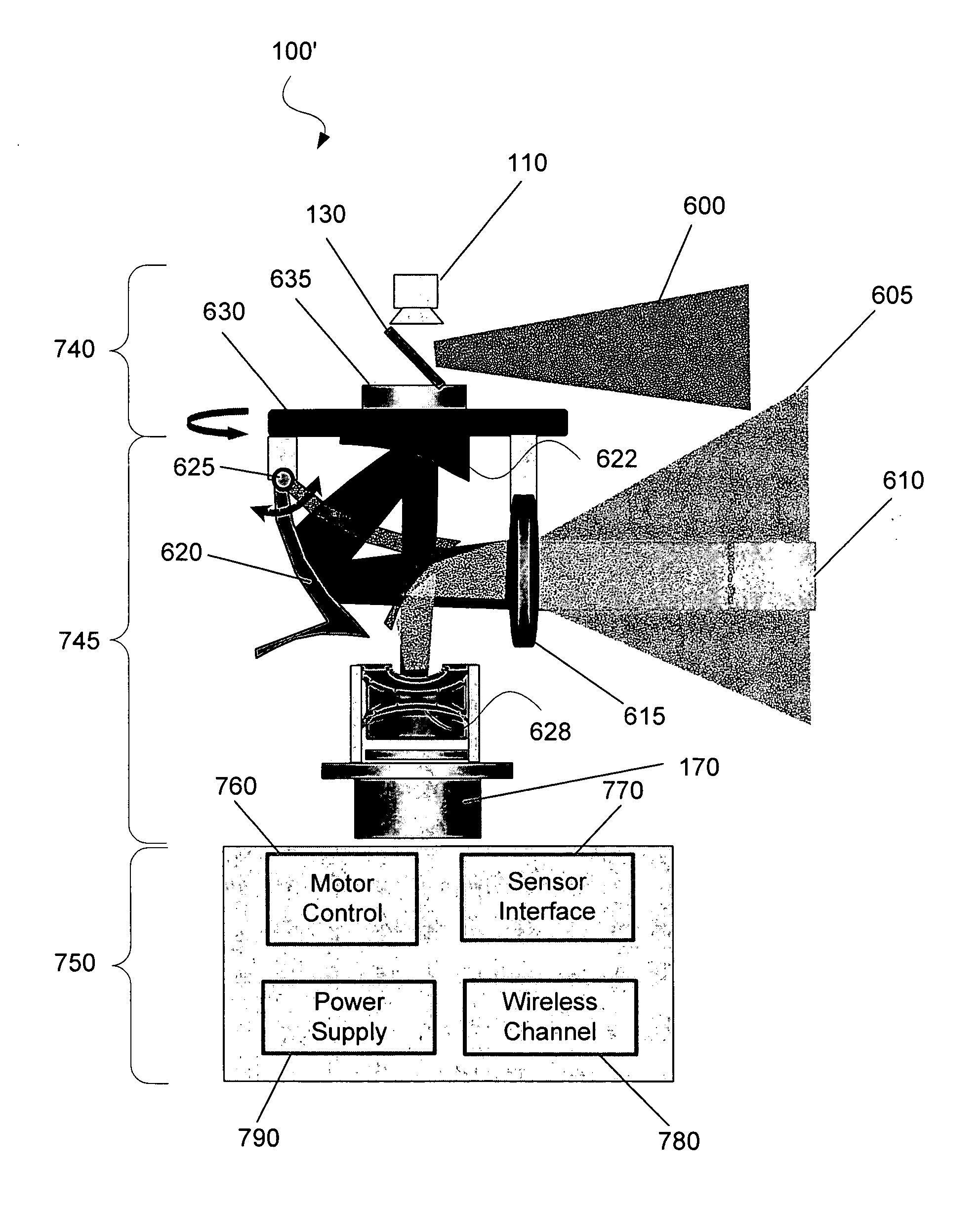
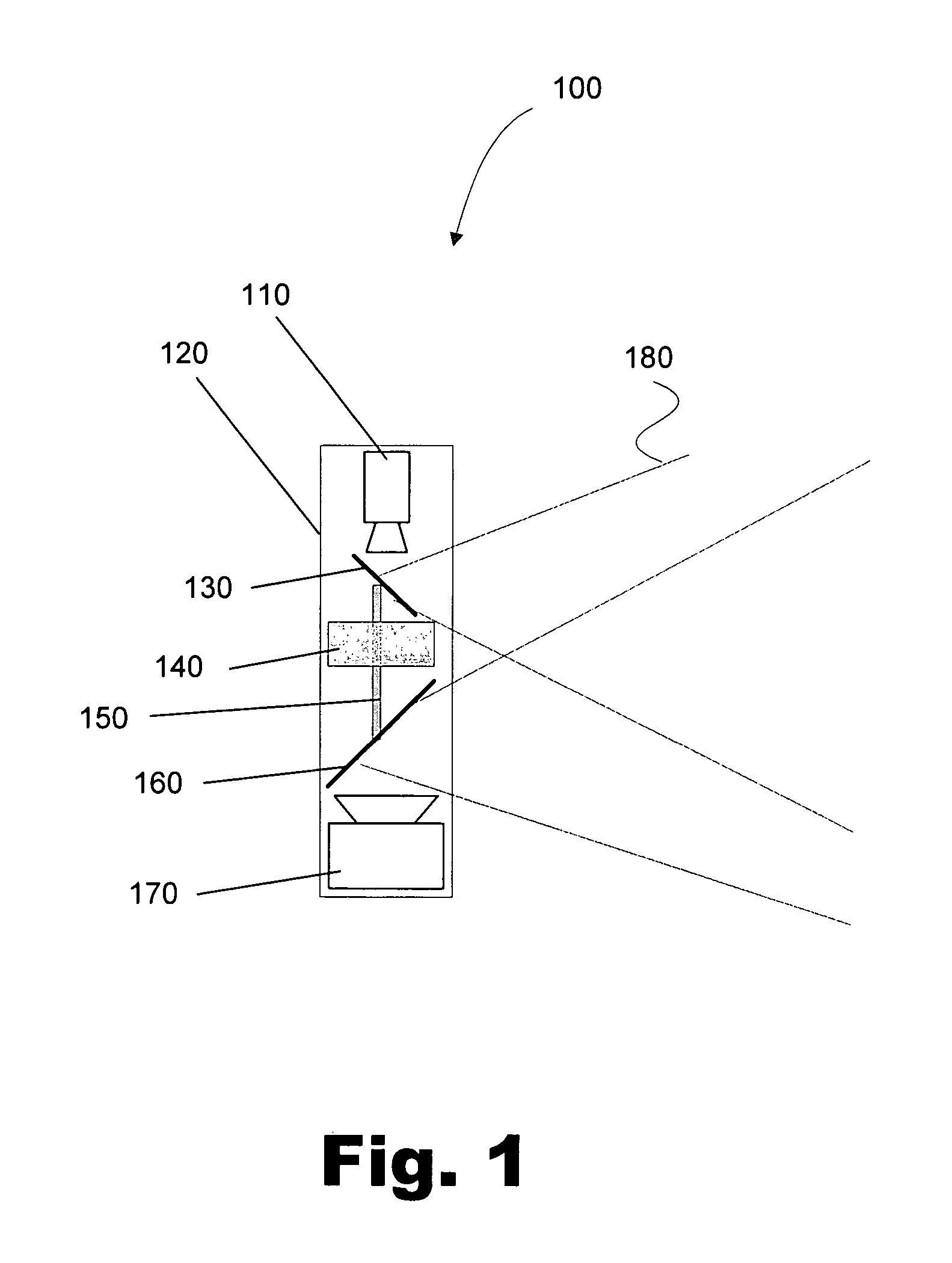
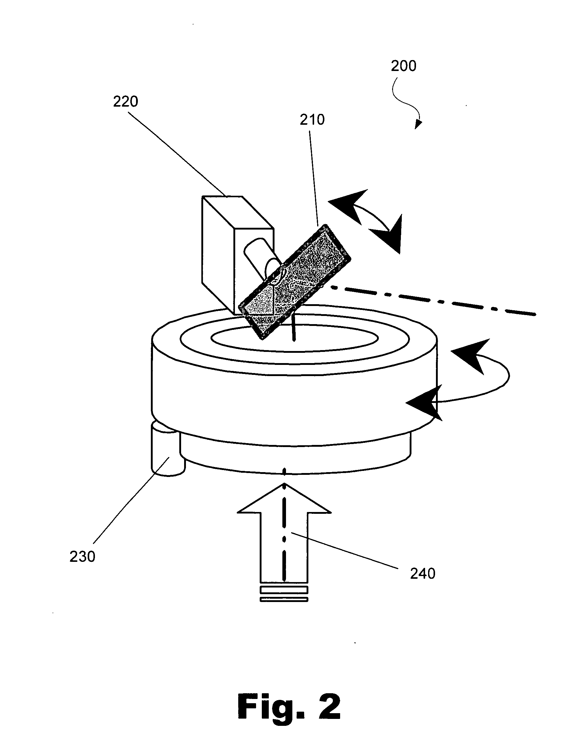
A number of exemplary systems, methods, and applications for utilizing a smart surveillance system are disclosed herein. More specifically, the present system and method relate to devices and methods that control a reflective material (mirror) to adjust the optical path of one or more substantially stationary optical sensors. By controlling the orientation of the reflective material rather than varying the position of the optical sensor, the present surveillance device has lower power requirements, a reduced size, and reduced weight when compared to traditional surveillance devices. A number of exemplary embodiments, optical surveillance configurations, and control and integration protocol are described in further detail below.

As used in the present specification and the appended claim, the term “optical sensor” is meant to be understood broadly as any sensor configured to detect variations in optical light waves. The optical light waves may be present in any spectrum including, bu...


PUM


Abstract

A radiation surveillance sensor system includes a radiation responsive sensor, a lightweight, radiation reflective member for selectively adjusting the incident radiation path to the sensor, and power means for controlling the position of the reflective member to achieve pan, tilt, or zoom functions for obtaining predetermined selectable view locations of the sensor. Similarly, a method for selectively controlling deflection of radiation from a field to be monitored by generating a 360 degree panoramic field of view includes the steps of fixedly positioning a radiation sensor for receiving radiation from a field to be observed, movably positioning a mirror-like surface for selectively reflecting radiation from the field to be observed towards the sensor, and rotatably driving the reflective mirror to selectively reflect radiation from the mirror to the fixedly mounted sensor to achieve up to a 360 degree panoramic view.

Description

FIELD The present specification relates to imaging mechanisms. More specifically, the present system and method relate to devices that utilize a reflective material to control the viewing direction and / or field-of-view of an optical sensor. BACKGROUND Security and surveillance are important to both individuals and companies. Traditionally, surveillance has been performed in person or using an image recording device such as an optical sensor monitoring a typically well lit area. More recently, night-vision technologies have allowed for the relatively easy surveillance of an object or area located in an obscure location. Additionally, traditional surveillance devices have developed the ability to rotate and / or vertically modify the viewing area of the image recording device using a combination of pan, tilt, and zoom capabilities. There are currently a number of pan, pan-tilt, and pan-tilt-zoom camera systems available that involve the control of a small motor to physically move an ...

Claims


Application Information

Patent Timeline
IPC IPC(8): G08B13/196
CPCG08B13/19608G08B13/1963G08B13/19632Y10T74/20207G08B13/19647H04N5/23238H04N5/332G08B13/19643H04N23/698H04N23/11
Inventor GENG, Z JASONTUNNELL, C. DAVID
Owner TECHNEST HLDG
Why Eureka
Try Eureka