Linear motor with magnet rail support, end effect cogging reduction, and segmented armature

a linear motor and magnet rail technology, applied in the field of linear motors, can solve the problems of unfavorable magnetic force exerted on the magnet rail, bending of the rail, and exacerbate unfavorable unfavorable unfavorable unfavorable unfavorable unfavorable unfavorable unfavorable unfavorable unfavorable unfavorable unfavorable unfavor

Inactive Publication Date: 2005-02-10
PARKER INTANGIBLES LLC
View PDF55 Cites 13 Cited by
  • Summary
  • Abstract
  • Description
  • Claims
  • Application Information

AI Technical Summary

Benefits of technology

[0015] According to another aspect of the invention, a linear armature yoke is provided which includes a relatively long yoke having a front face comprising a plurality of slots f

Problems solved by technology

Despite the recognized advantages associated with known linear motors, there have been a number of drawbacks.
Failure to provide such equal airgap results in uneven magnetic forces being exerted on the magnet rail.
In the case of a relatively thin magnet rail, this can result in a bending of the rail which further exacerbates uneveness in the air gap and the magnetic forces exerted on the magnet rail by the respective yokes.
Still another drawback associated with linear motors is “cogging”.
In general, cogging forces i

Method used


Image

  • Linear motor with magnet rail support, end effect cogging reduction, and segmented armature
  • Linear motor with magnet rail support, end effect cogging reduction, and segmented armature
  • Linear motor with magnet rail support, end effect cogging reduction, and segmented armature

Examples


Embodiment Construction

[0031] The present invention will now be described with reference to the drawings, wherein like reference numerals are used to refer to like elements throughout.

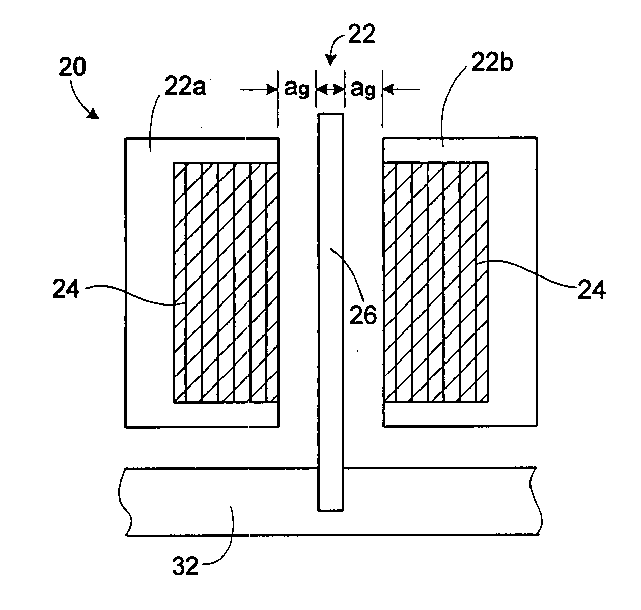
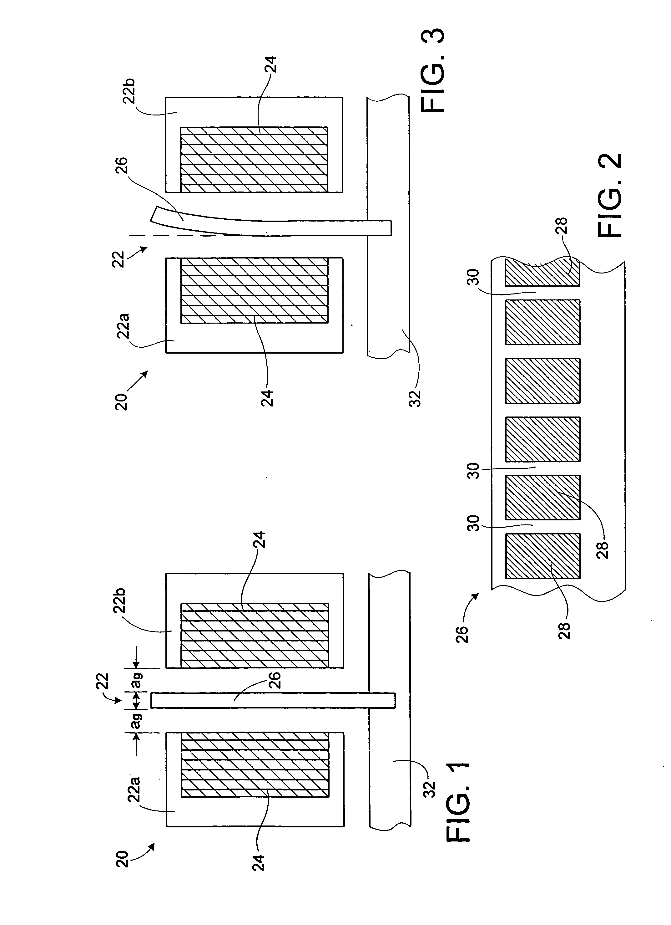
[0032] Referring initially to FIG. 1, a cross-section of a double-sided linear motor 20 is shown schematically. The motor 20 includes an armature 22 made up of armature yokes 22a and 22b. Each armature yoke 22a, 22b includes a set of coil windings 24 wound between teeth of the respective yokes. The armature yokes 22a, 22b are positioned on opposite sides of a magnet rail 26 by a motor support carriage (not shown). Ideally, the teeth of the armature yokes 22a, 22b are separated from the magnet rail 26 by a predetermined air gap “ag” on each side.

[0033]FIG. 2 is a side view of the magnet rail 26. As shown, the magnet rail 26 includes a plurality of plate-like permanent magnets 28. The magnets 28 are positioned linearly along the rail 26 at a predefined pitch with corresponding gaps 30 therebetween. The magnet rail 26 may be ...


PUM


Abstract

A linear motor is provided which includes members for engaging a magnet rail to prevent bending of the magnet rail. Such members may include a wheel or sliding block, for example. The members exert a force proximate an upper edge of the magnet rail to counter potential bending of the magnet rail during operation of the motor, and thereby avoid substantial variations in the air gaps. Furthermore, an armature yoke is provided which includes at least one partial tooth at one end of the armature yoke for reducing an end effect cogging of the linear motor armature in relation to a magnet rail along which the armature will run. In addition, an armature yoke is provided which includes multiple segments which are held end-to-end via fasteners. Such fasteners may serve as part of the magnetic flux path. A support strip may be provided to reduce bowing.

Description

TECHNICAL FIELD [0001] The present invention relates generally to linear motors, and more particularly to a linear motor which offers improved performance and manufacturabilty. BACKGROUND OF THE INVENTION [0002] Linear motors are known in the art. According to a typical configuration, the linear motor includes an armature which makes up the stator. The armature includes a yoke made up of a pack of ferromagnetic laminations. The yoke includes a plurality of teeth arranged at a predefined pitch, with a plurality of slots respectively separating the teeth. The armature further includes coil windings wound around the teeth and housed in the respective slots. [0003] The linear motor also includes a magnet rail which forms the rotor. The magnet rail includes a plurality of plate-like permanent magnets. The magnets are positioned linearly along the rail at a predefined pitch with corresponding gaps therebetween. The armature travels along the length of the magnet rail with the teeth of the...

Claims


Application Information

Patent Timeline
IPC IPC(8): H02K41/03
CPCH02K41/031
Inventor HARNED, TIMOTHY J.HUARD, STEVEN ROGER
Owner PARKER INTANGIBLES LLC
Why Eureka
Try Eureka