
Axial flux permanent magnet generator/motor

a permanent magnet generator and axial flux technology, applied in the direction of dynamo-electric machines, magnetic circuit rotating parts, magnetic circuit shape/form/construction, etc., can solve the problems of high cost and complex manufacture of such a stator

Inactive Publication Date: 2005-02-10
VLAAMSE INSTELLING VOOR TECHNOLOGISCH ONDERZOEK NV VITO
View PDF12 Cites 17 Cited by
  • Summary
  • Abstract
  • Description
  • Claims
  • Application Information

AI Technical Summary

Benefits of technology

[0029]FIG. 9 represents a view of a ring of laminated magnetic material,

Problems solved by technology

The manufacture of such a stator is complex as well as expensive, especially in small series.

Method used


Image

  • Axial flux permanent magnet generator/motor
  • Axial flux permanent magnet generator/motor
  • Axial flux permanent magnet generator/motor

Examples


Embodiment Construction

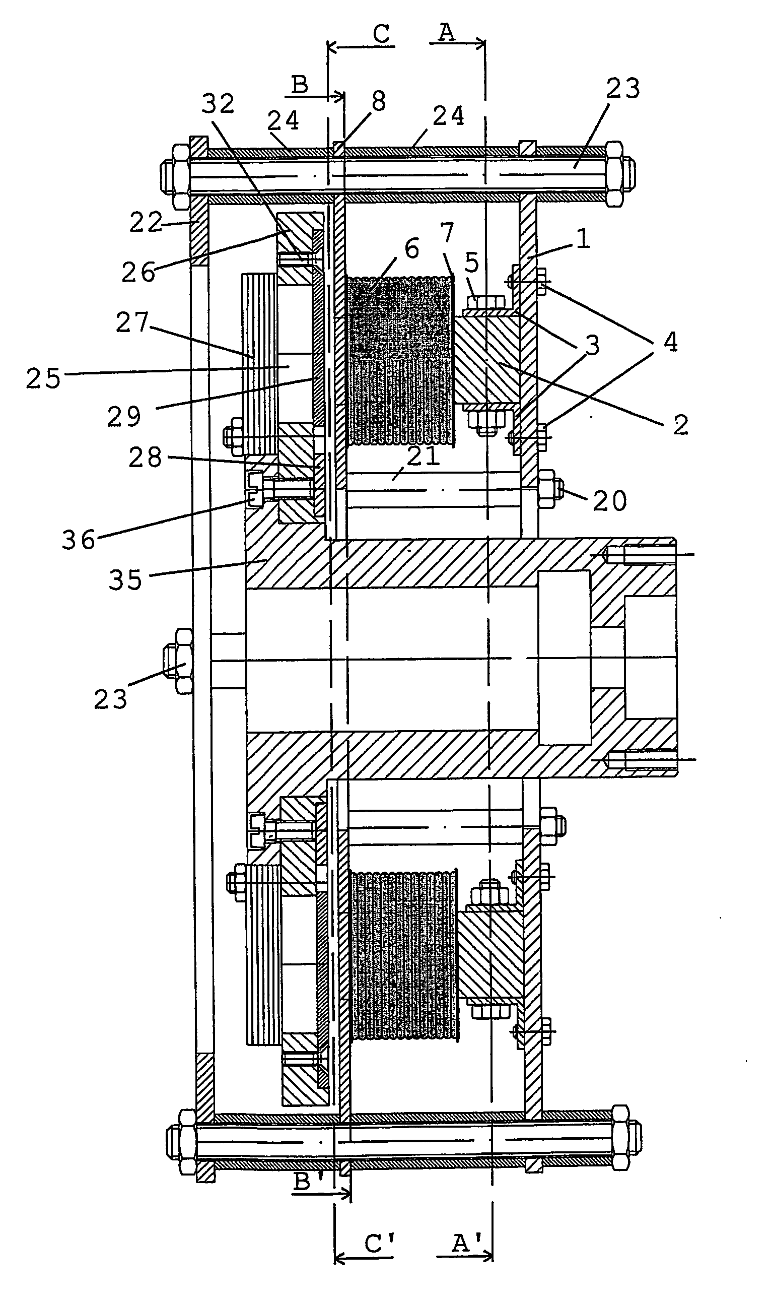
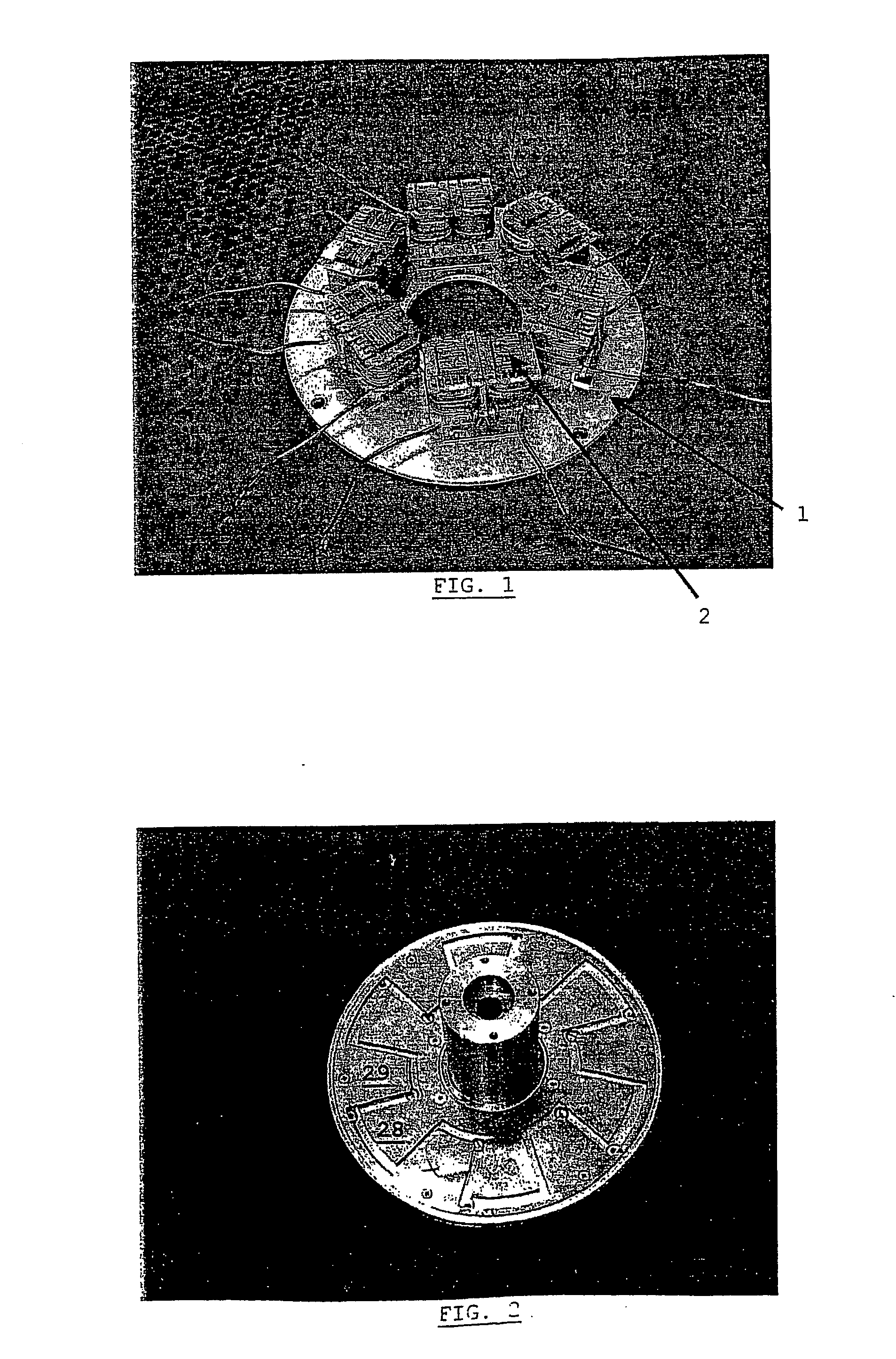
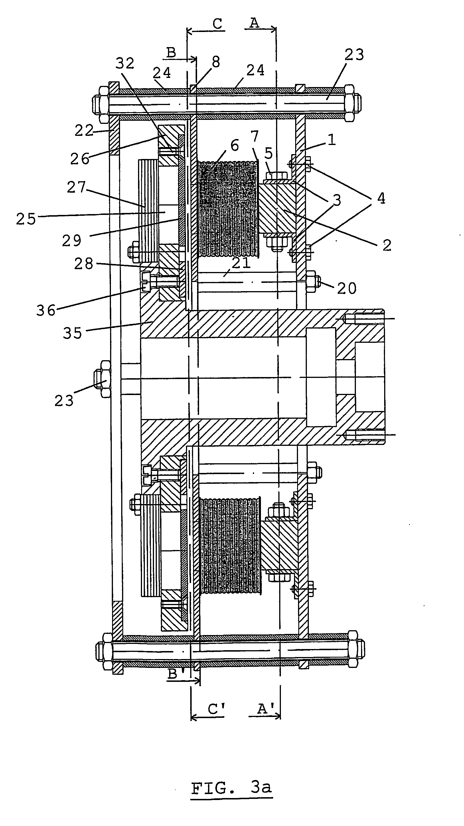
[0031] The present invention generally presents a concept for an axial flux permanent magnet generator / motor, wherein a number of cores 2 are attached onto a disc 1, in order to form the stator. The disc 1 is preferably circular shaped, but the function of this disc can be performed by any plate made of a non-magnetic material. Also, the disc or plate 1 may be made of a magnetic material, which is covered by an insulation. The photograph of FIG. 1 illustrates a partly assembled stator according to the invention, comprising six U-cores. The fact that separate cores are used allows the use of standard cores, thus leading to a straightforward and inexpensive design.

[0032] The main problem of using such a design however, resides in the large fluctuation of the air gap between such a stator and the rotor, which is to be placed facing the cores on the stator. The rotor will preferably comprise a number of permanent magnets of a given form, at equal distances on a circle which is co-axial...


PUM


Abstract

The present invention is related to a permanent magnet electrical generator / motor comprising a stator, a rotor, a rotational axis and an air gap between stator and rotor so that the magnetic flux across said air gap is essentially oriented along said rotational axis, said rotor preferably comprising a plurality of permanent magnets to form rotor poles, said generator / motor being characterised in that said stator comprises a disc (1), and a plurality of magnetic cores (2), said cores (2) being attached to said disc (1) by attachment means, said cores comprising coils (6) wound round the legs of said cores. Furthermore, said machine comprises means for distributing the flux across the air gap between rotor and stator. Preferably, this takes on the form of flux distribution plates (28,29), placed between rotor and stator.

Description

FIELD OF THE INVENTION [0001] The present invention is related to an axial flux permanent magnet generator / motor, for example for use with internal combustion engines, where this type of machine is incorporated in the flywheel. STATE OF THE ART [0002] The axial flux permanent magnet generator and motor has been described in various forms. It consists of a stator comprising a plurality of coils, and a rotor comprising several permanent magnets, wherein an air gap is present between stator and rotor. The notion of ‘axial flux’ is not always defined in the same way. In this text, the expression ‘axial flux’ is related to machines wherein the flux across the air gap is essentially parallel to the machine's rotational axis. [0003] The closest prior art when it comes to this type of machine has been disclosed in the publication entitled ‘An Axial Flux Interior PM Synchronous Machine’, by D. H. Kang et al., ICEM 2000, 28-30 Aug. 2000. It comprises two stators, each made as a single hollow ...

Claims


Application Information

Patent Timeline
IPC IPC(8): H02K1/27H02K21/24
CPCH02K21/24
Inventor VAN TICHELEN, PAULPEETERS, EEF
Owner VLAAMSE INSTELLING VOOR TECHNOLOGISCH ONDERZOEK NV VITO
Learn More