

Antenna coil and transmission antenna
- Summary
- Abstract
- Description
- Claims
- Application Information
AI Technical Summary
Benefits of technology
Problems solved by technology
Method used
Image

Examples
Example
OPTIMUM FORM TO EMBODY THE INVENTION
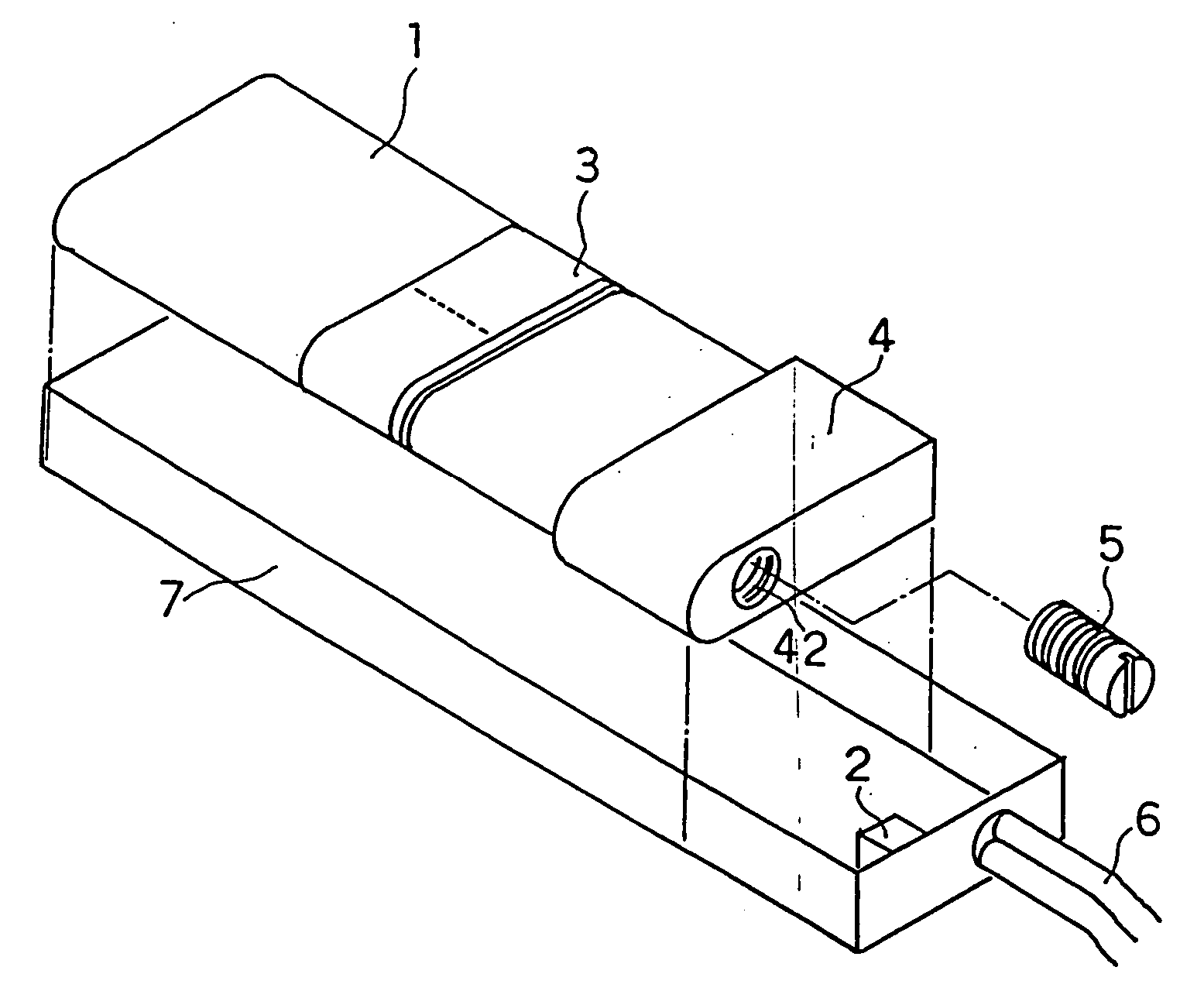
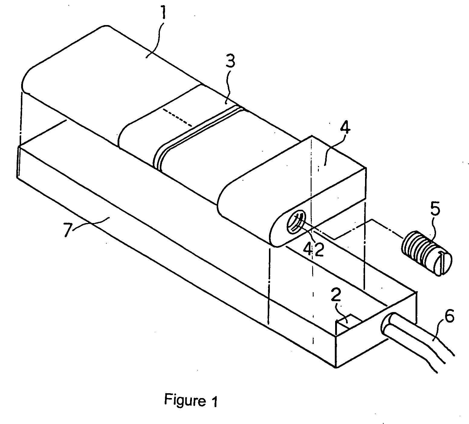
[0024] As depicted by the perspective diagram of FIG. 1 and the main component top-down view diagram of FIG. 2, respectively, the transmission antenna of the present embodiment is outfitted with a ferrite core (1) and a capacitor (2). An antenna coil (3) is mounted by being wound onto the ferrite core (1). The core (1) forms a flat bar and mated to one of its lengthwise ends is a small flat piece of plastic (a non-magnetic material) that serves as a distance adjuster (4). Namely, formed in one end of the distance adjuster (4) is an indented part (41) whose size corresponds to an end of core (1). One end of core (1) is inserted into, and thus mated to, this indented part.
[0025] A screw hole (42) facing the core (1) end mated to the aforementioned indented part (41) is formed in the end face of that side of the distance adjuster (4) wherein the indented part (41) is not formed. A screw (5) with a small core made of, for example, ferrite is threade...
PUM
 Abstract
Description
Claims
Application Information