Eureka AIR delivers breakthrough ideas for toughest innovation challenges, trusted by R&D personnel around the world.

Tire forming mold

a technology of forming molds and tires, applied in the field of tire forming molds, can solve the problems of generating defective molding, affecting the quality of tire components, and difficult to discharge air in a place, so as to reduce the air resistance of laminated blades, shorten the diametrical distance of tires, and construct simple

Inactive Publication Date: 2011-01-25
TOYO TIRE & RUBBER CO LTD
View PDF5 Cites 11 Cited by
  • Summary
  • Abstract
  • Description
  • Claims
  • Application Information

AI Technical Summary

Benefits of technology

[0008]The present invention is made by taking the actual condition mentioned above into consideration, and an object of the present invention is to provide a tire forming mold which can lower air resistance in a laminated blade so as to smoothly discharge air, has an air discharging effect which does not depend on an arranged position of the laminated blade, and can easily set and regulate a micro gap of the laminated blade.Means for Solving the Problems
[0010]In accordance with the tire forming mold of the present invention, the air pressed into the depression at a time of curing the tire is fed to the exhaust chamber through the micro gap of the laminated blade, and is subsequently fed to the mold back face or the mold split surface through the exhaust hole so as to be discharged to the outer side of the mold. Since the exhaust chamber is formed in the inner portion of the pocket by fitting the block into the pocket provided in the concave manner in the depression of the molding surface, the tire diametrical distance in which the air moves within the micro gap is shortened. As a result, in cooperation with the effect of the air chamber achieved by the exhaust chamber, it is possible to reduce the air resistance in the laminated blade so as to efficiently and smoothly discharge the air while keeping such a micro gap that the rubber can not pass through.
[0011]Further, in the present invention, whatever position of the depression the arranged position of the laminated blade is, it is possible to feed the air to the mold back face or the mold split face through the exhaust hole. Even if it is away from the mold back face or the mold split surface, it is possible to secure a smooth discharge of the air, and the air discharging effect does not depend on the arranged position of the laminated blade. Further, since the laminated blade is held by the block fitted to the pocket, it becomes easy to set and regulate the micro gap in comparison with the case that the laminated blade is directly embedded in the depression such as the related art. In addition, in a case where a clogging caused by the curing gas, the rubber or the like is generated in the laminated blade, it is only necessary to clean or replace the laminated blade by detaching the block from the molding surface. Accordingly, a maintaining work is easy.
[0013]The laminated blade having the structure mentioned above is constructed by folding one metal thin plate so as to superpose, and energizing the bent end portions in the direction in which they separate from each other. The energization of the bent end portion as mentioned above may include a utilization of a spring back at a time of folding the thin plate so as to elastically deform. Further, since the side in which the bent end portions of the laminated blade are superposed is pinched by the slit provided in the block, it is possible to suitably hold the laminated blade and secure the micro gap. In addition, it is possible to easily set and regulate the micro gap by regulating an interval of the slit and a thickness of the laminated blade.
[0015]In accordance with the structure mentioned above, since the laminated blade is held by the base portion of the block as mentioned above, it is possible to widely shorten the tire diametrical distance in which the air moves within the micro gap, and it is possible to better reduce the air resistance in the laminated blade. Further, since the exhaust chamber is surrounded by the base portion, the bottom wall of the pocket and a pair of protruding portions, the exhaust chamber comes to a state in which it is suitably interrupted from the molding surface, and it is possible to securely feed the air fed to the exhaust chamber through the micro gap to the exhaust hole so as to discharge the air to the outer side of the mold.
[0016]In the present invention, the block provided in the plate shape can be fitted to the pocket in such a manner as to be supported to the step portion provided in the side wall of the pocket. In accordance with the structure mentioned above, since the shape of the block becomes simple, it is possible to construct simply and with a low cost.

Problems solved by technology

At this time, air existing between the tread surface and the molding surface is compressed into the depression for forming the land portion, however, if the curing is carried out with the air left, there is a problem that a concave chip called as lightness is generated in the tread surface and a defective molding is generated.
However, since a lot of rubber projections called spew are formed in the tread surface, an ablating work is necessary and there is a problem that the dropout spew is mixed as a foreign material into the mold, which results in a defect.
However, in the case of using the laminated blade in which one end portion is exposed to the molding surface and the other end portion is exposed to a mold back face, such as the following patent document 1, since a tire diametrical distance in which the air moves within the micro gap becomes long and air resistance is increased, an air discharging effect may be obstructed, and thus there is room for further improving this.
On the other hand, if the gap of the laminated blade is enlarged in order to improve this, the rubber makes an intrusion into the gap, so that the same problem as that in a case where the vent hole is provided is generated.
Further, in the case of using a laminated blade in which a side end is exposed to the molding surface and an end portion is exposed to a mold split surface (for example, a split surface between segments) such as the following patent document 2, there is a tendency that it becomes hard to discharge the air in a place which is away from the mold split surface, and there is a defect that the air discharging effect depends on an arranged position of the laminated blade.
Further, since the laminated blade is directly embedded in the depression in both the following patent documents, a work for setting and regulating the micro gap is complicated.

Method used


Image

  • Tire forming mold
  • Tire forming mold
  • Tire forming mold

Examples


Embodiment Construction

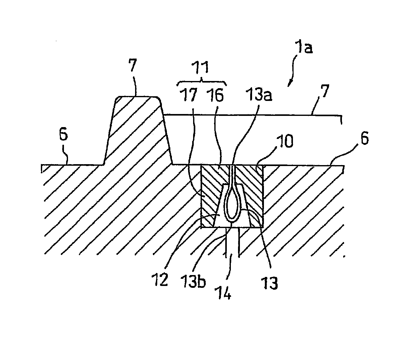
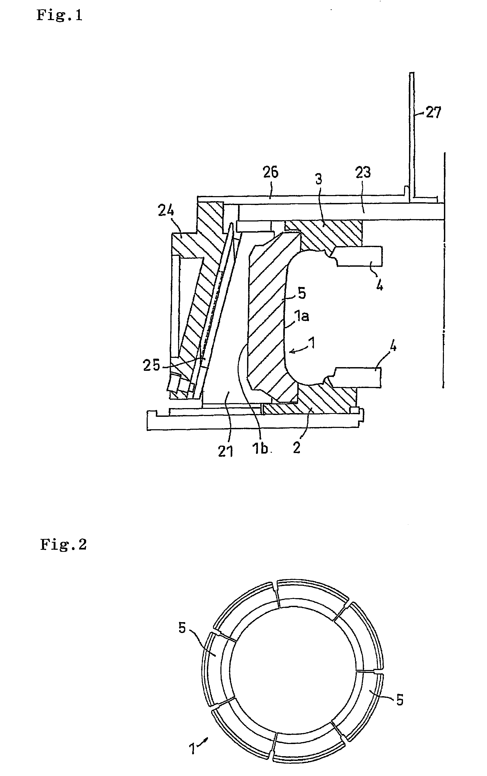
[0049]An embodiment of the present invention will be explained with reference to the drawings. FIG. 1 is a vertical cross sectional view showing an example of a tire forming mold in accordance with the present invention, and shows a mold clamping state. In FIG. 1, a green tire (not shown) is set in such a manner that a tire axial direction is arranged up and down, a right direction in FIG. 1 corresponds to an inner side in a tire diametrical direction, and a left direction in FIG. 1 corresponds to an outer side in the tire diametrical direction. In the present embodiment, there is shown an example in which the forming mold is of a segmented type.

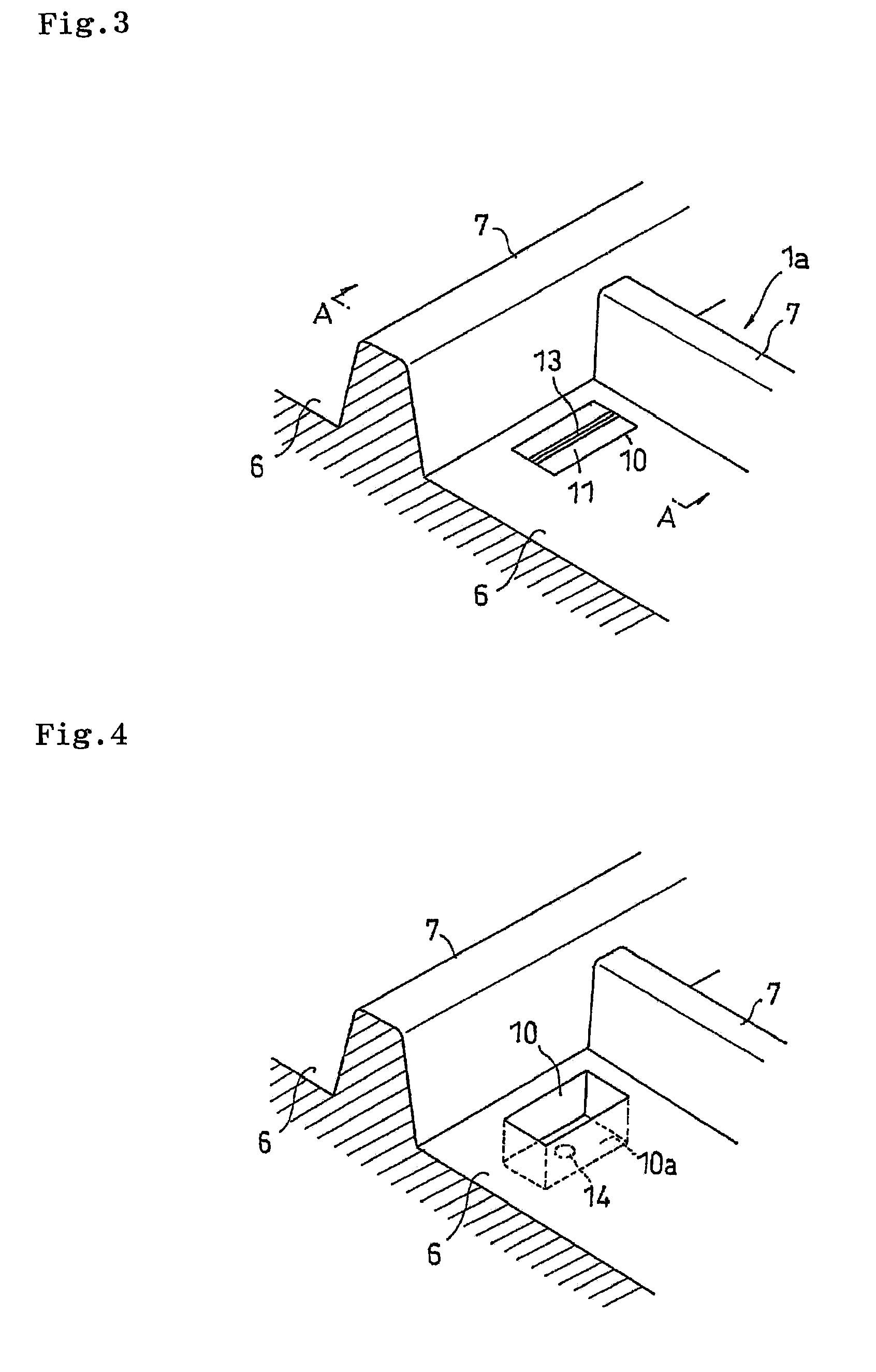
[0050]The tire forming mold (hereinafter, often refer simply to as a forming mold) is provided with an annular mold portion 1 having the molding surface 1a brought into contact with a tread portion of the tire, a lower mold portion 2 with which a lower side wall portion comes into contact, and an upper mold portion 3 with which an upper side...


PUM

PropertyMeasurementUnit
depthaaaaaaaaaa
depthaaaaaaaaaa
thicknessaaaaaaaaaa

Abstract

A tire forming mold in which a depression for forming a land portion of a tread surface is provided in a molding surface forming a tread pattern of a tire. The tire forming mold has a pocket provided in the depression, a block fitted into the pocket to form an exhaust chamber in an inner portion of the pocket and holding a laminated blade, which is formed by superposing thin plates, so that one end portion is exposed to the molding surface and the other end portion is exposed to the exhaust chamber, and an exhaust hole having one end portion is communicated with the exhaust chamber and the other end portion is communicated with a mold back face or a mold split face.

Description

TECHNICAL FIELD[0001]The present invention relates to a tire forming mold which is used for curing a tire and in which a depression for forming a land portion of a tread surface is provided in a molding surface forming a tread pattern of the tire.BACKGROUND ART[0002]Generally, at a time of curing the tire, the molding surface of the tire forming mold is pressed against the tread surface, and the tread pattern corresponding to a concavo-convex shape of the molding surface is formed. At this time, air existing between the tread surface and the molding surface is compressed into the depression for forming the land portion, however, if the curing is carried out with the air left, there is a problem that a concave chip called as lightness is generated in the tread surface and a defective molding is generated. Accordingly, it is important to suitably discharge the air compressed into the depression out of the mold.[0003]As a lightness countermeasure, it is general to employ a method of pi...

Claims


Application Information

Patent Timeline
Patent Type & Authority Patents(United States)
IPC IPC(8): B29C33/10
CPCB29C33/10B29D30/0629B29D2030/0617Y10S425/812
Inventor OHARA, MASAAKI
Owner TOYO TIRE & RUBBER CO LTD
Why Eureka
Eureka Blog
Learn More