

Organic EL display device and driving circuits
- Summary
- Abstract
- Description
- Claims
- Application Information
AI Technical Summary
Benefits of technology
Problems solved by technology
Method used
Image

Examples
Embodiment Construction
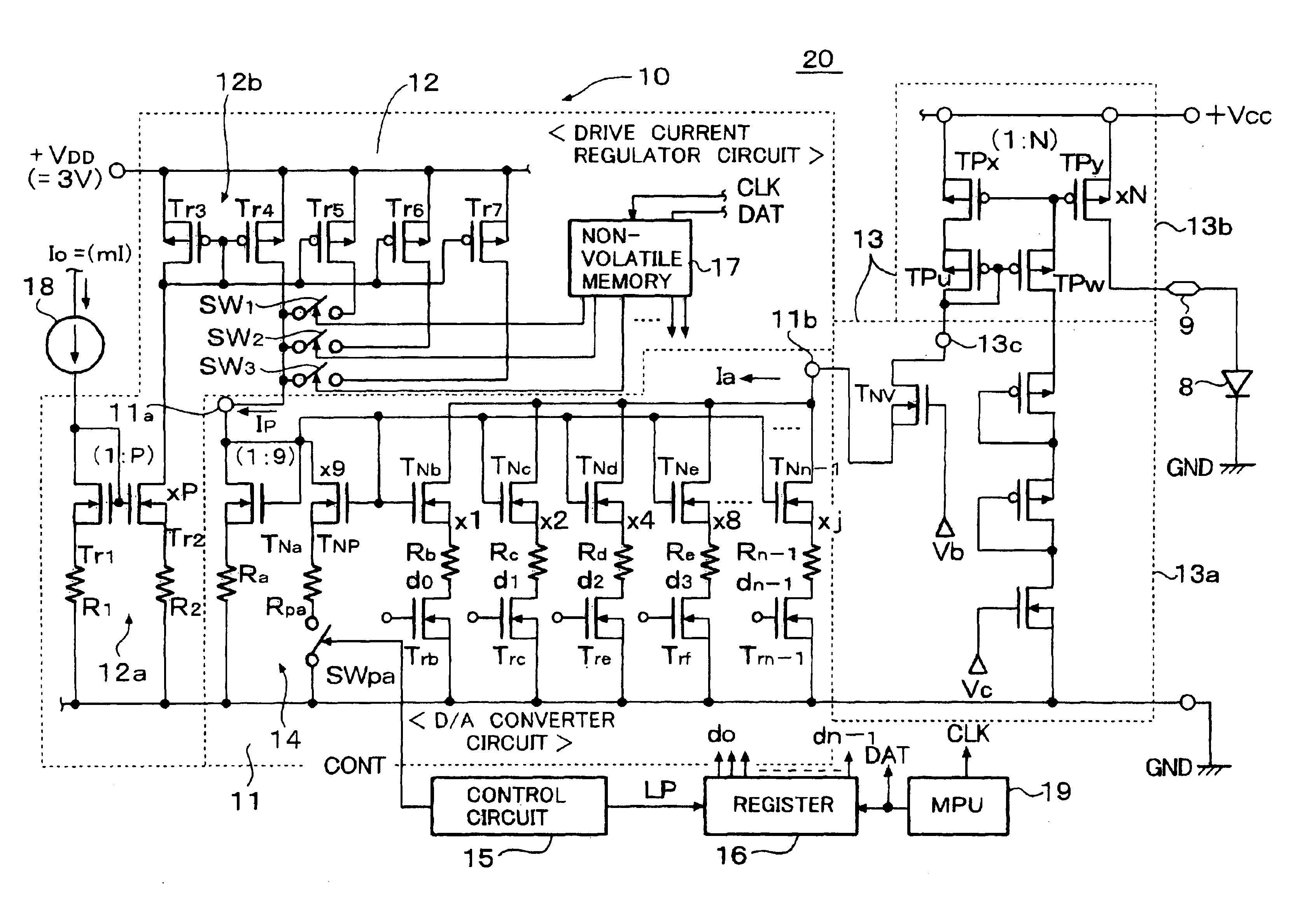
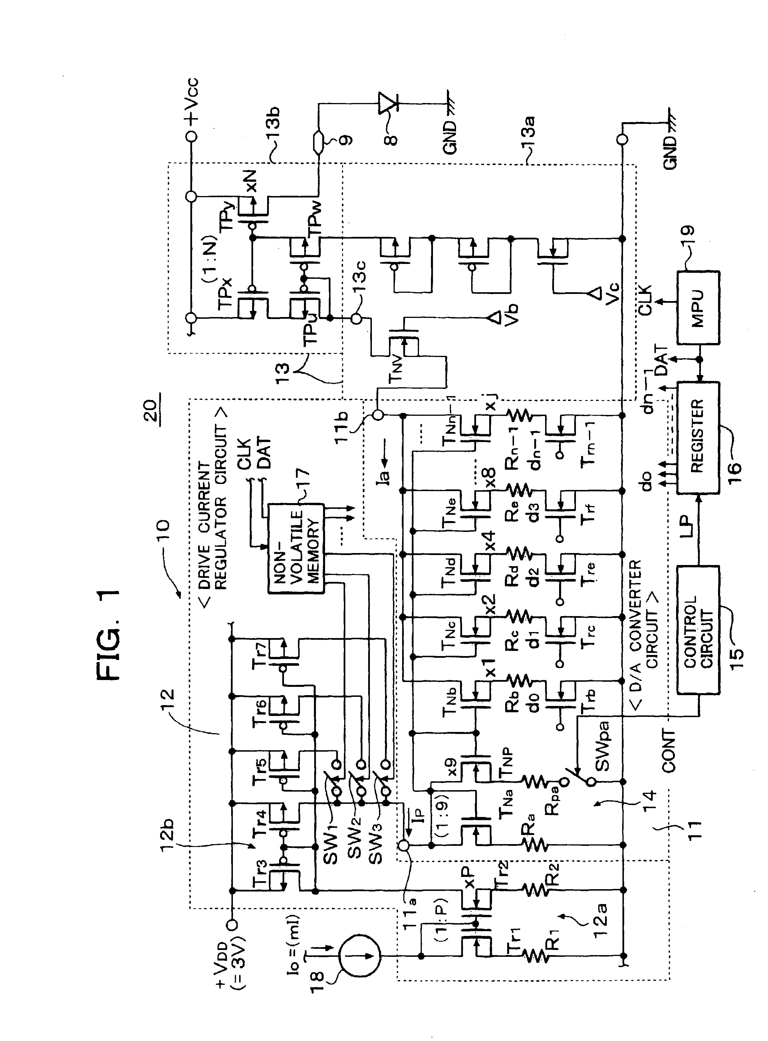
[0030]FIG. 1 is a block circuit diagram of a column driver 20 of an organic EL element drive circuit, according to an embodiment of the present invention. In FIG. 1, the column driver 20 corresponds to a combination of the k-time drive current generator circuits 82 and the n current mirror output circuits 83 for outputting the N-time outputs, shown in FIG. 4, and is provided for every terminal pin of the organic EL display panel.
[0031]A circuit depicted by a reference numeral 10 corresponds to a combination of the k-time drive current generator circuit 82 shown in FIG. 4 having a D / A converter circuit 11 and generates a drive current corresponding to a display data. A reference numeral 12 depicts a drive current regulator circuit, 13 a current-mirror type current output circuit, 14 a peak current generator circuit, 15 a control circuit, 16 a register, 17 a non-volatile memory and 18 a constant current source. The constant current source 18 outputs a output current (Io=mI) correspond...
PUM
 Abstract
Description
Claims
Application Information