Chroma upsampling method and apparatus therefor

a chroma upsampling and video data technology, applied in the field of video data processing, can solve the problems of difficult display of satellite or cable television receivers, inability to find a complete solution, and display of very noticeable color artifacts, so as to prevent the chroma upsampling error

Inactive Publication Date: 2005-02-10
CSR TECH INC
View PDF9 Cites 50 Cited by
  • Summary
  • Abstract
  • Description
  • Claims
  • Application Information

AI Technical Summary

Problems solved by technology

Many MPEG compression based satellite or cable television receivers also display this difficulty.
The problem stems from the improper conversion of the “4:2:0” chroma format (where each of the two chroma components have half the number of samples per line and half the number of lines as the luma component), used for example by the more popular subsets of the MPEG video standards, to the “4:2:2” chroma format (where each of the two chroma components have half the number of samples per line and the same number of lines as the luma component) or “4:4:4” chroma format (where each of the two chroma components have the same number of samples per line and the same number of lines as the luma component) required in order to create an image suitable for viewing on standard interlaced or progressive scan television displays.
Although methods are known in the prior art that, to some degree, alleviate the artifacts caused by this problem, a complete solution has not been available in the past.
This is because there may be movement between the two fields, resulting in the display of very noticeable color artifacts.
Unfortunately, most prior art MPEG decoders ignore the “progressive_frame” flag, and only perform one kind of interpolation in order to make an MPEG integrated circuit chip simpler and thereby reduce cost.
Also, there are often errors with the MPEG flags.
Effectively, adjacent pairs of chroma scan lines are switched, which produces the characteristic jagged / streaky visual effect known as the chroma upsampling error.
Although this approach may help prevent color bleeding at sharp image transitions, when progressively scanned images using lower resolution chroma formats are upsampled to higher resolution chroma formats, it adds significant complexity when interlaced images are being processed.
For interlaced video formats, the separation of adjacent rows in the video data increases, requiring much larger data storage if this technique is to be used.
Therefore, from a practical standpoint, it does not help reduce the chroma upsampling error.

Method used


Image

  • Chroma upsampling method and apparatus therefor
  • Chroma upsampling method and apparatus therefor
  • Chroma upsampling method and apparatus therefor

Examples


Embodiment Construction

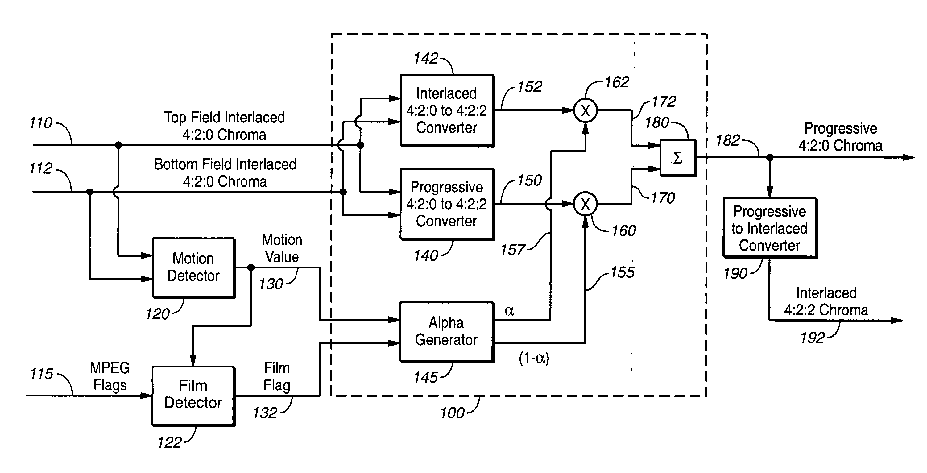
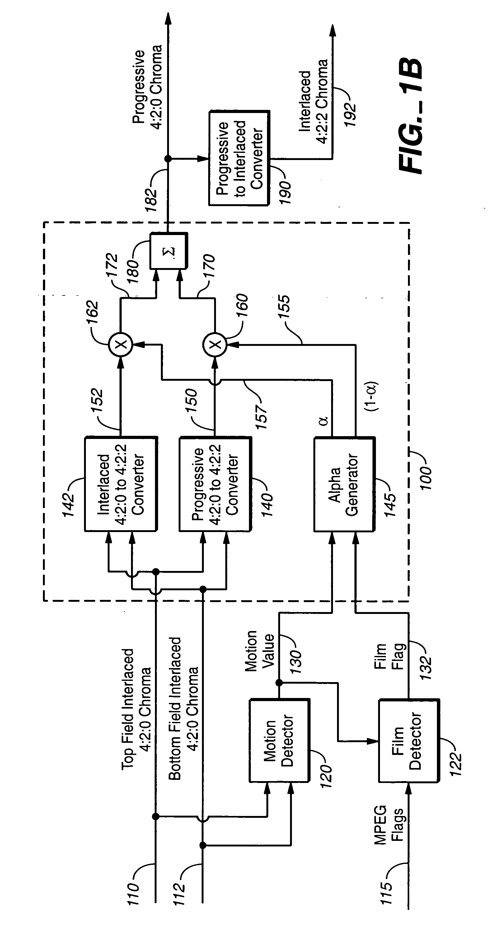
[0032] Certain embodiments of the present invention and their advantages are best understood by referring to the drawings. Like reference numerals are used for like and corresponding parts of the various drawings.

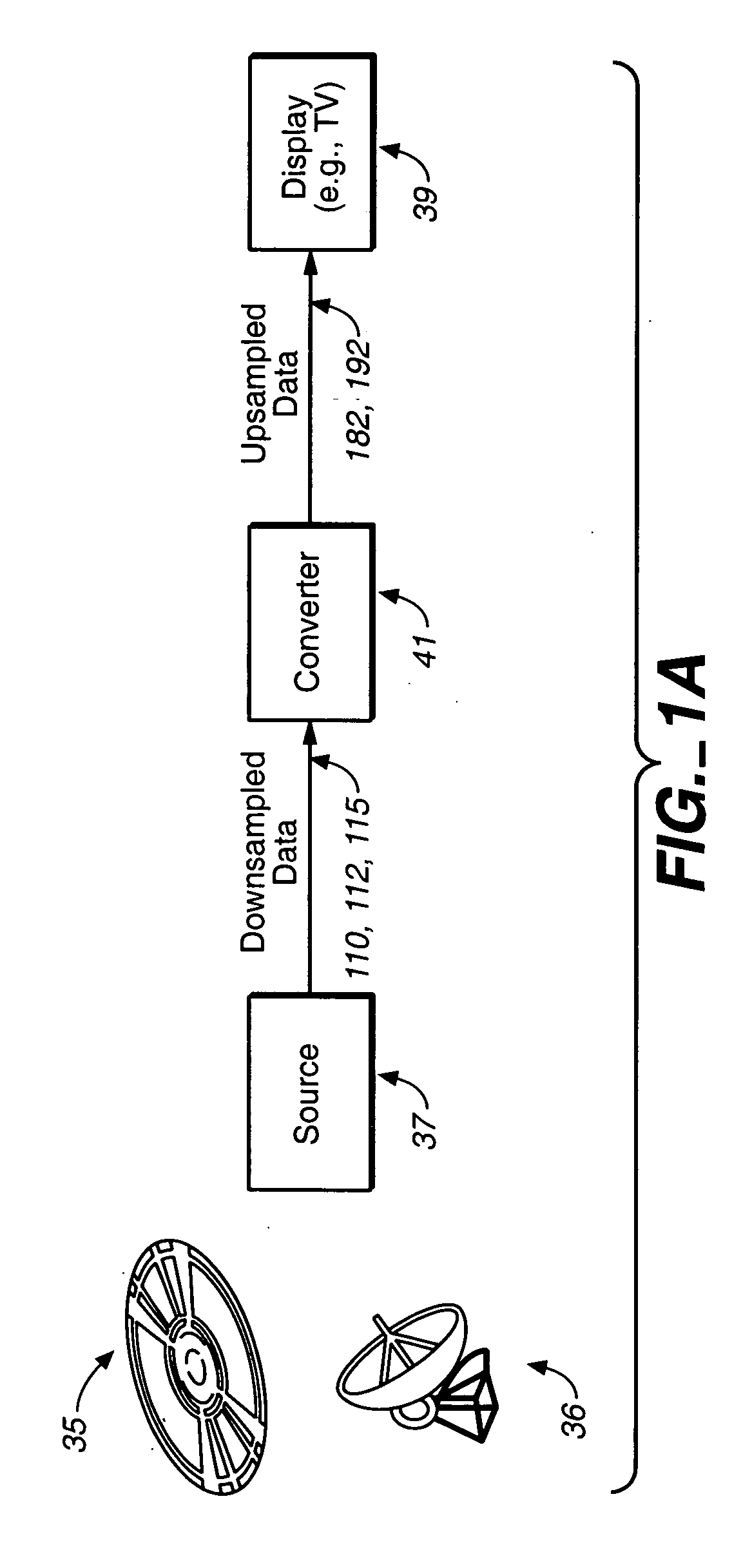
[0033] In a principle aspect, the present invention presents chroma upsampling methods and apparatus that minimizes the picture processing artifacts described in the Background section and provide a solution that can be readily integrated for example into a single chip DVD processor integrated circuit. An exemplary embodiment performs chroma vertical upsampling for conversion of the “4:2:0” format chroma information used in many applications of digital video, to the “4:2:2” or “4:4:4” format. This conversion is required so that video encoders can effect the display of this chroma information with a minimum of visible artifacts. The present invention carries out such upsampling on a pixel by pixel basis. This chroma vertical upsampling is performed as a function of the amou...


PUM


Abstract

A unique method for chroma vertical upsampling used, for example, for conversion of the “4:2:0” format chroma information used in many applications of digital video, to the “4:2:2” or “4:4:4” format, is presented. This conversion is required so that video encoders can effect the display of this chroma information with a minimum of visible artifacts. The present invention carries out chroma vertical upsampling on a pixel by pixel basis. This chroma vertical upsampling is performed as a function of the amount of motion associated with each pixel as detected between 2 or more fields, and the field, frame and progressive sequence characteristics of the incoming video signal data.

Description

BACKGROUND OF THE INVENTION [0001] This invention relates, generally, to the processing of video data and, more specifically, to the elimination of picture processing artifacts visible on images displayed from data with vertically sub-sampled chroma. [0002] A thorough background article on chroma upsampling error entitled “DVD Benchmark—A Special Report—The Chroma Upsampling Error on DVD Players—April 2001 by Don Munsil and Stacey Spears”, was published by “hometheaterhifi.com” in April 2001, since updated, and is hereby incorporated by reference. [0003] The method was invented to address a problem of the quality of displayed MPEG compressed images which can be found in nearly every DVD player currently being offered for sale. Many MPEG compression based satellite or cable television receivers also display this difficulty. The effect is seen as jagged edges on brightly colored objects that appear in the display of the decoded image. The problem stems from the improper conversion of ...

Claims


Application Information

Patent Timeline
Patent Type & Authority Applications(United States)
IPC IPC(8): H04N5/44H04N9/64H04N11/20
CPCH04N5/4401H04N9/64H04N7/0122H04N21/426
Inventor LEONE, PASQUALECHOW, WING-CHIGILL, AHARON
Owner CSR TECH INC
Why Eureka
Try Eureka