Interchangeable lens, interchangeable lens system and camera system

a technology of interchangeable lenses and interchangeable lenses, which is applied in the direction of mountings, instruments, camera body details, etc., can solve the problems of ccd sensor or cmos sensor having the same size as the 35 mm silver-haloid film, unable to reach luminous flux, back end of interchangeable lens may interfere with the quick return mirror,

Active Publication Date: 2005-02-10
CANON KK
View PDF5 Cites 27 Cited by
  • Summary
  • Abstract
  • Description
  • Claims
  • Application Information

AI Technical Summary

Benefits of technology

[0010] It is one of objects of the present invention to provide an interchangeable lens, interchangeable lens system and camera system capable of preventing, even when an attempt is made to mistakenly

Problems solved by technology

However, an electronic image-pickup element such as CCD sensor or CMOS sensor having the same size as the 35 mm silver-haloid film is very expensive, and therefore the use of an image-pickup element (e.g., APS-C size image-pickup element) is becoming the mainstream instead of the 35 mm film.
However, once the aforementioned short back-focus interchangeable lens is mounted on a 35 mm film camera body or a digital camera supporting an image circle larger than the interchangeable lens, the back end of the interchangeable lens may interfere with the quick return mirror.
Furthermore, allowing an interchangeable lens dedicated to a digital camera having a short ba

Method used


Image

  • Interchangeable lens, interchangeable lens system and camera system
  • Interchangeable lens, interchangeable lens system and camera system
  • Interchangeable lens, interchangeable lens system and camera system

Examples


embodiment 1

[0085] [Embodiment 1]

[0086]FIG. 1 to FIG. 6 show a camera system including an interchangeable lens and camera body which is Embodiment 1 of the present invention.

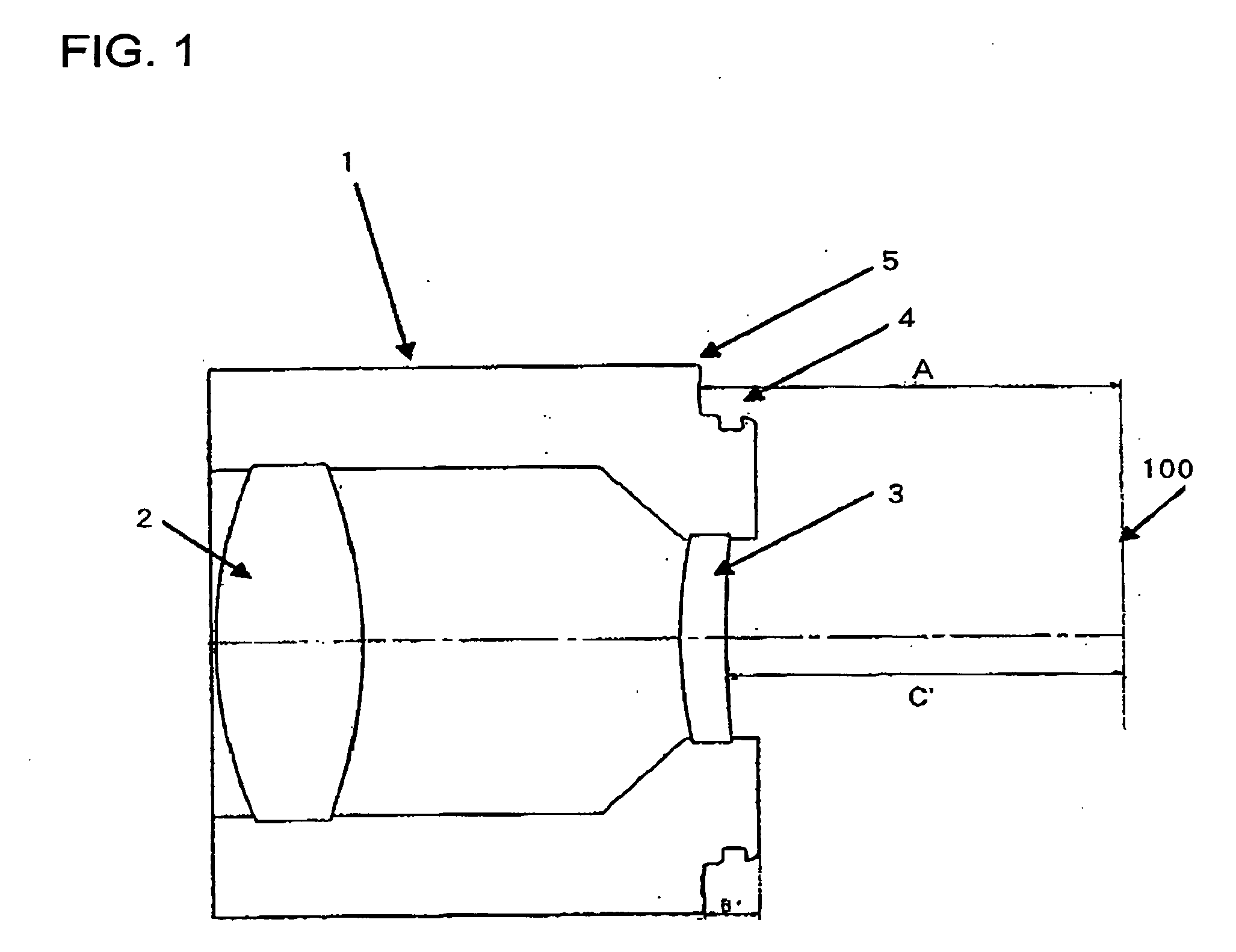
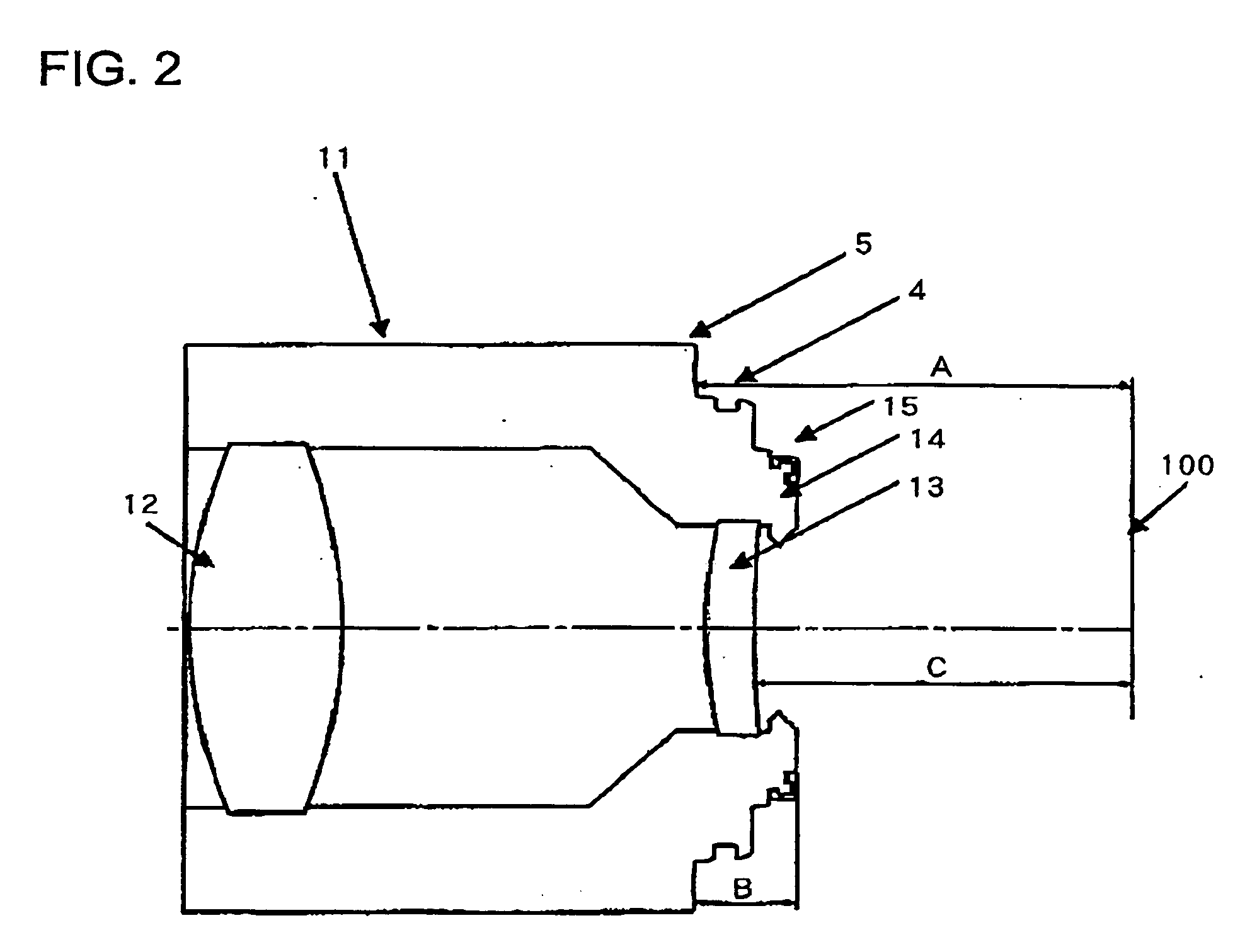
[0087]FIG. 1 is a cross-sectional view showing a first interchangeable lens 1 for a 35 mm film camera, which holds a first optical lens 2 and a second optical lens 3 in a lens barrel. On the back end side, bayonet lugs 4 for bayonet coupling with a camera body are provided and the bayonet lugs 4 are disposed closer to an image-pickup surface 100 than a mount reference surface 5 located at a distance of a flange back “A” from the image-pickup surface 100. Here, the portion protruding from the mount reference surface 5 including the bayonet lug 4 toward the image-pickup surface corresponds to the protruding portion of the first interchangeable lens 1.

[0088] Furthermore, the distance from the mount reference surface 5 to the end face of the bayonet lug 4 on the image-pickup surface 100 side is represented by “B′”. Furthermor...

embodiment 2

[0108] [Embodiment 2]

[0109] Using FIG. 11 to FIG. 18, a camera system which is Embodiment 2 of the present invention will be explained. FIG. 11 to FIG. 14 are cross-sectional views showing main parts of the camera system. FIG. 15 and FIG. 16 are cross-sectional views and front views showing first and second interchangeable lenses of this embodiment. FIG. 17 and FIG. 18 are cross-sectional views and front views showing the first and second camera bodies of this embodiment.

[0110] Reference numerals 120 and 130 denote interchangeable lenses, 120 denotes a second interchangeable lens having a small image size on the film surface (or photoreceiving surface of an image-pickup element) and 130 denotes a first interchangeable lens having a large image size. Reference numerals 140 and 150 denote camera bodies, 140 denotes a second camera body which allows mounting of the first and second interchangeable lenses 130, 120 and 150 denotes a first camera body which does not allow mounting of the...

embodiment 3

[0131] [Embodiment 3]

[0132] With new reference numerals assigned to the structure of the interchangeable lenses and cameras explained in Embodiment 1 and Embodiment 2, Embodiment 3 will be explained using FIG. 19 to FIG. 41 in detail below. Here, a case where the first and second cameras are digital cameras provided with an image-pickup element will be explained. In the following explanations, “front” means an object side and “back” will refer to an image plane or image-pickup element side.

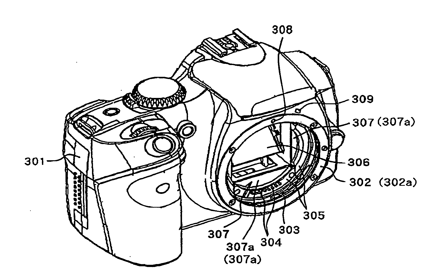
[0133]FIG. 19, FIG. 26, FIG. 28 and FIG. 29 show a first camera (camera body) 201. The first camera 201 is provided with a ring-shaped mount 202 for mounting a first interchangeable lens, which will be described later, on the front. The front end face of this mount 202 constitutes a reference surface (mount reference surface) 202a when a first interchangeable lens is mounted.

[0134] Inside the mount 202 (inner diameter side), bayonet lugs 203 for bayonet coupling with the first interchangeable le...


PUM


Abstract

An interchangeable lens is disclosed which prevents the camera body and interchangeable lens from being damaged even if an attempt is made to erroneously mount therebetween. The interchangeable lens is a second interchangeable lens whose flange back is the same as that of a first interchangeable lens and includes a protruding portion protruding from a mount reference surface. The protruding amount of the protruding portion is set when the second interchangeable lens has a specific phase relationship with a first camera, so that the protruding portion contacts a first wall portion of the first camera, and is set when the second interchangeable lens has a phase relationship with the first camera other than the specific phase relationship and a bayonet lug of the second interchangeable lens contacts a bayonet lug of the first camera, so that the protruding portion is away from the first wall portion.

Description

BACKGROUND OF THE INVENTION [0001] 1. Field of the Invention [0002] The present invention relates to interchangeable lenses with different amounts of protrusion from a mount reference surface toward an image plane used for a camera system including a plurality of cameras having the same mount structure, and the camera system. [0003] 2. Description of the Related Art [0004] With the advance of digitization of cameras in recent years, there is a proposal on a single-lens reflex camera system whose lenses are interchangeable made up of single-lens reflex digital cameras which inherit the sameness in a mount shape to allow conventional interchangeable lenses to be used on one hand, and which replace a 35 mm silver-haloid film by an electronic image-pickup element such as a CCD sensor and CMOS sensor. However, an electronic image-pickup element such as CCD sensor or CMOS sensor having the same size as the 35 mm silver-haloid film is very expensive, and therefore the use of an image-picku...

Claims


Application Information

Patent Timeline
IPC IPC(8): G02B7/02G02B7/14G03B17/00G03B17/14G03B19/02
CPCG03B17/14G02B7/14
Inventor KOYAMA, ATSUSHITAMURA, MASAHISASUGITA, JUN
Owner CANON KK
Why Eureka
Try Eureka