Additional safety device for sear mechanism for firearms

Active Publication Date: 2005-02-17
FABBRICA DARMI PIETRO BERETTA SPA
View PDF4 Cites 12 Cited by
  • Summary
  • Abstract
  • Description
  • Claims
  • Application Information

AI Technical Summary

Benefits of technology

[0016] Another object of the present invention is to provide a sear mechanism which is lighter and may be made of elements which comprise a plastic material.
[0017] Another object of the invention is to permit the use of a low actuation force

Problems solved by technology

Such a mobile sear element constitutes a delicate detail of the sear mechanism, since it is stressed mechanically and has a complex form, and it is thus generally made from metal.
Since the

Method used


Image

  • Additional safety device for sear mechanism for firearms
  • Additional safety device for sear mechanism for firearms
  • Additional safety device for sear mechanism for firearms

Examples


Example

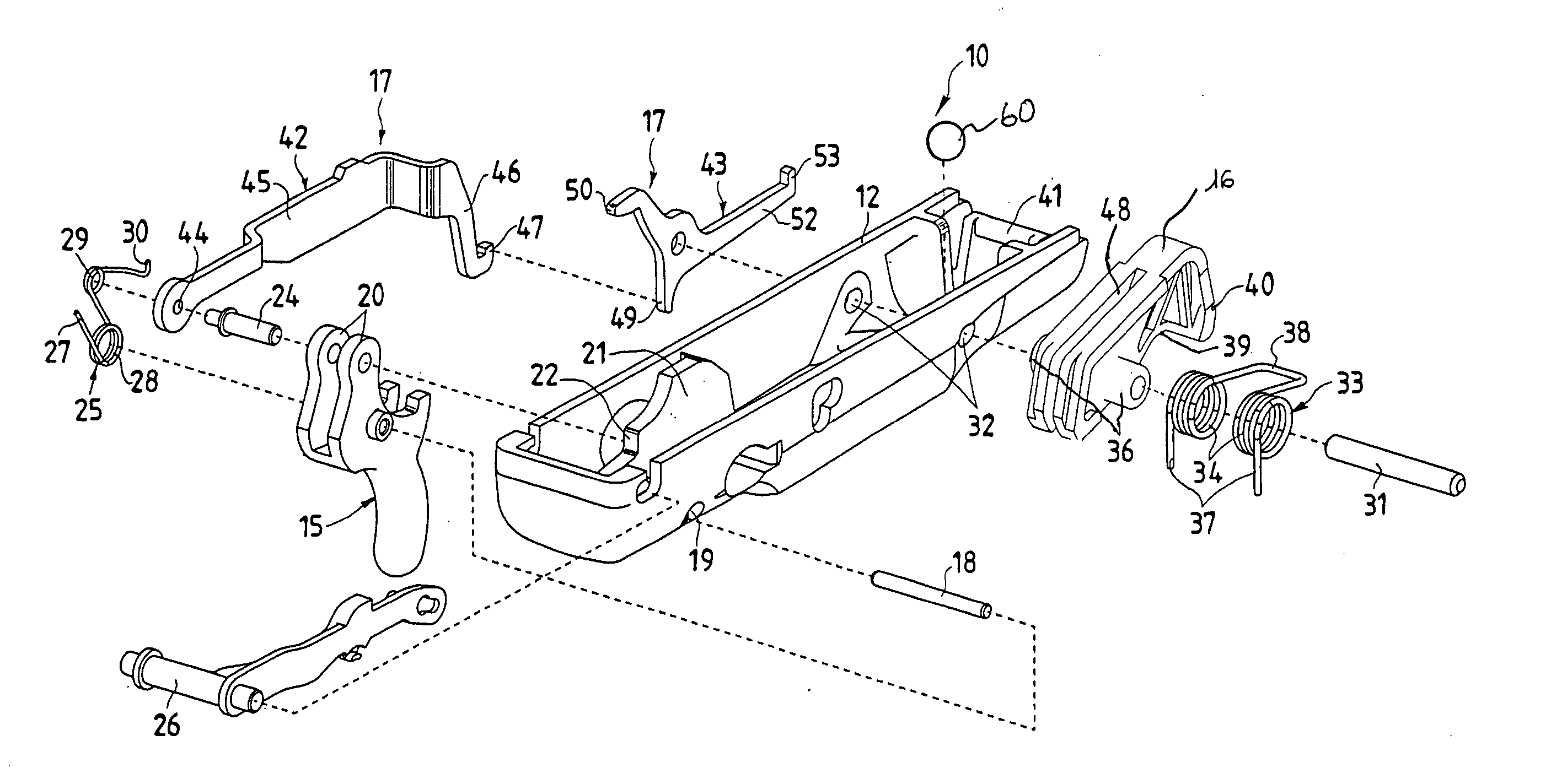
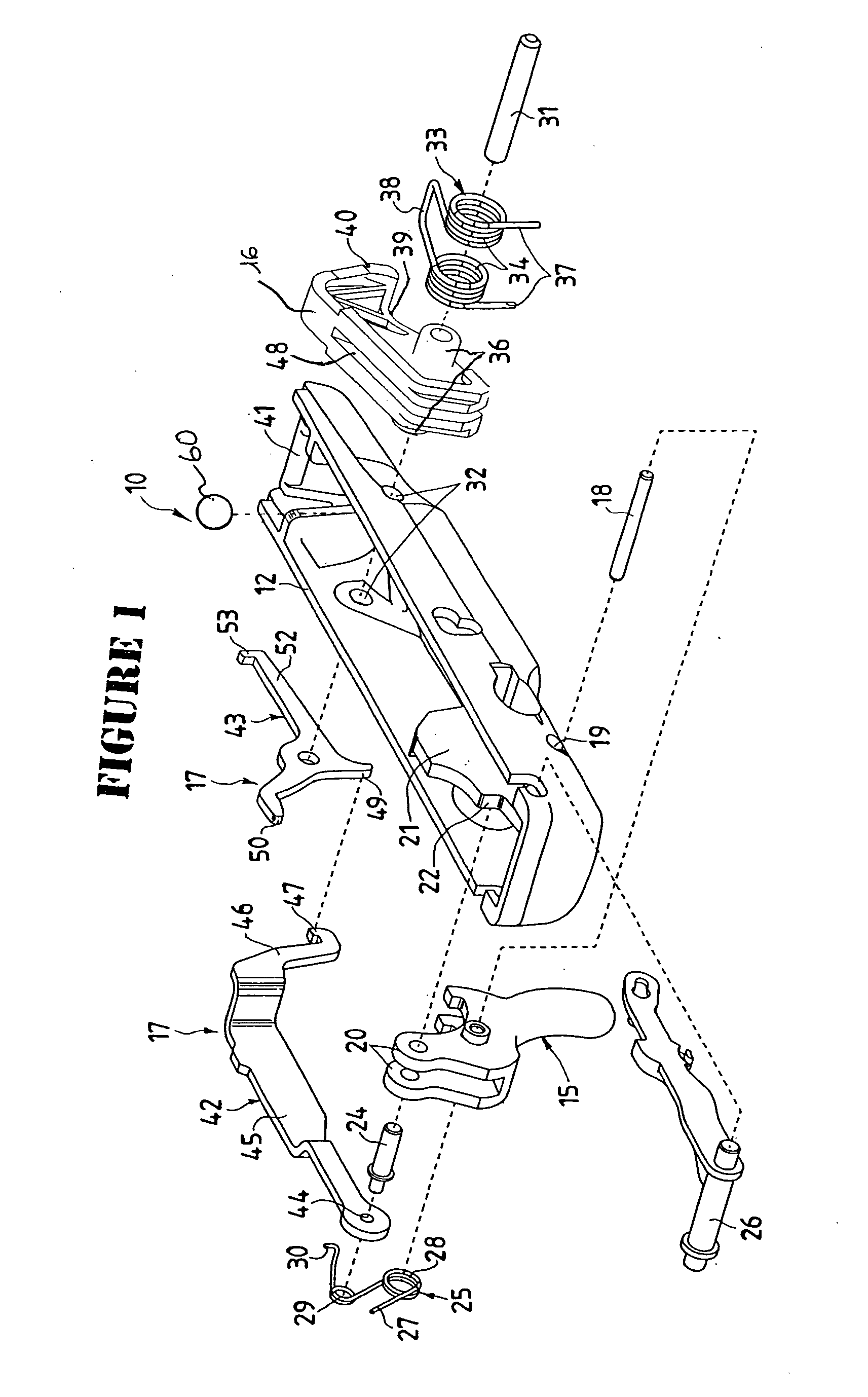
[0029] As shown in FIG. 1, the sear mechanism 10 for firearms comprises a sear box 12, which can be inserted in the structure of a firearm, for example in the stock or fore-end.

[0030] The firearm comprises a well known breechblock carrier 13 carrying a firing pin 14, as partially shown in FIGS. 3-6.

[0031] On the sear box 12 are mounted a trigger 15, a hammer 16 and a sear device 17 which when controlled by trigger 15, releases the hammer 16 from a cocking position A in engagement on sear box 12 and a striking position B against the firing pin 14. As shown in FIGS. 1-6, the trigger 15 is mounted at the sear box 12 through a rotation pin 18, housed in a hole 19, so as to be protruding below the front part of the sear box 12.

[0032] The trigger 15 consists of an upper forked portion 20 mounted straddling an abutment rib 21 of the sear box 12. A connection pin 24, to which the sear device 17 is hinged, is applied to the upper forked portion 20 of the trigger. In the sear mechanism 10,...


PUM


Abstract

A sear mechanism for firearms comprises a sear box 12, and an additional safety device to prevent the hammer 16 from releasing accidentally and to fire under the action of inertial forces acting along the direction of the axis of the barrel in case of impact of the firearm, the additional safety device being an interposing element 60 which is slidably mounted below the firing pin latch 43 in a housing having a first inclined plane element 63 and a second inclined plane element 63a which are arranged between lateral walls 62 to form a seat 61 which holds element 60 in a first position where it does not interfere with the operation of the firing pin latch 43 but allows said element 60 to move into a position where it prevents the pin latch 43 from moving downwardly to disengage hammer 16.

Description

[0001] This application is a continuation in part of Ser. No. 10 / 390,939, filed Mar. 18, 2003, which claims the priority of Italian Application Serial No. MI2002A 000623, filed Mar. 26, 2002.BACKGROUND OF THE INVENTION [0002] (1) Field of the Invention [0003] The present invention refers to a new additional safety device for a sear mechanism for firearms. [0004] (2) Description of Related Art [0005] In general, the field of portable, semi-automatic or automatic firearms foresees different solutions for the sear mechanism, which comprises a mobile element which holds the hammer in the cocking position. [0006] Following the voluntary pulling of the trigger, the mobile element frees the hammer and allows it to hit against a firing pin under the thrust of a preloaded elastic element. [0007] Such a mobile element can be realized, for example as a sear or as a sear pawl, pivoted at a fixed part of the body of the firearm and biased by an elastic element. To carry out its function such a m...

Claims


Application Information

Patent Timeline
IPC IPC(8): F41A19/44
CPCF41A17/72F41A19/44
Inventor BERETTA, UGO GUSSALLI
Owner FABBRICA DARMI PIETRO BERETTA SPA
Why Eureka
Try Eureka