Sliding-action magneto-mechanical injector throttling device

a magneto-mechanical and injector technology, applied in the field of vortex injectors, can solve the problems of high throttling ratio, inability to achieve, and significant engine performance loss

Inactive Publication Date: 2005-02-17
XILINX INC +1
View PDF5 Cites 4 Cited by
  • Summary
  • Abstract
  • Description
  • Claims
  • Application Information

AI Technical Summary

Benefits of technology

[0005] As the SLAMMIT sub-assemblies slide, flappers inside the sub-assemblies achieve the effective opening size of the injection orifices anywhere between fully open and fully closed, both of the maximum positions inclusive. The flappers match in number the injection orifices that are located on the injector's body and each flapper is of a shape and size to cover its corresponding orifice completely. In the SLAMMIT Device, the differential pressures between the manifolds and the combustion chamber are used to effect a secure seal that prevents fuel flow and oxidizer flow into the chamber when the Device is positioned in the fully-closed position.

Problems solved by technology

This approach is simple to implement but high throttling ratios (maximum mass flow-rate divided by minimum mass flow-rate) cannot be achieved via this approach without significant losses in engine performance.
The losses occur because the minimum allowed pressure drop across the injection orifices is not maintained at the entrance to the orifices.
However, this approach requires a breaching of the fuel manifold and using either an electrical or pneumatic actuator to drive the throttling mechanism via a mechanical link that passes through the breach.
A significant disadvantage of this method is the requirement for a robust sealing system at the manifold-to-mechanical link interface, giving rise to reliability issues.

Method used


Image

  • Sliding-action magneto-mechanical injector throttling device
  • Sliding-action magneto-mechanical injector throttling device
  • Sliding-action magneto-mechanical injector throttling device

Examples


Embodiment Construction

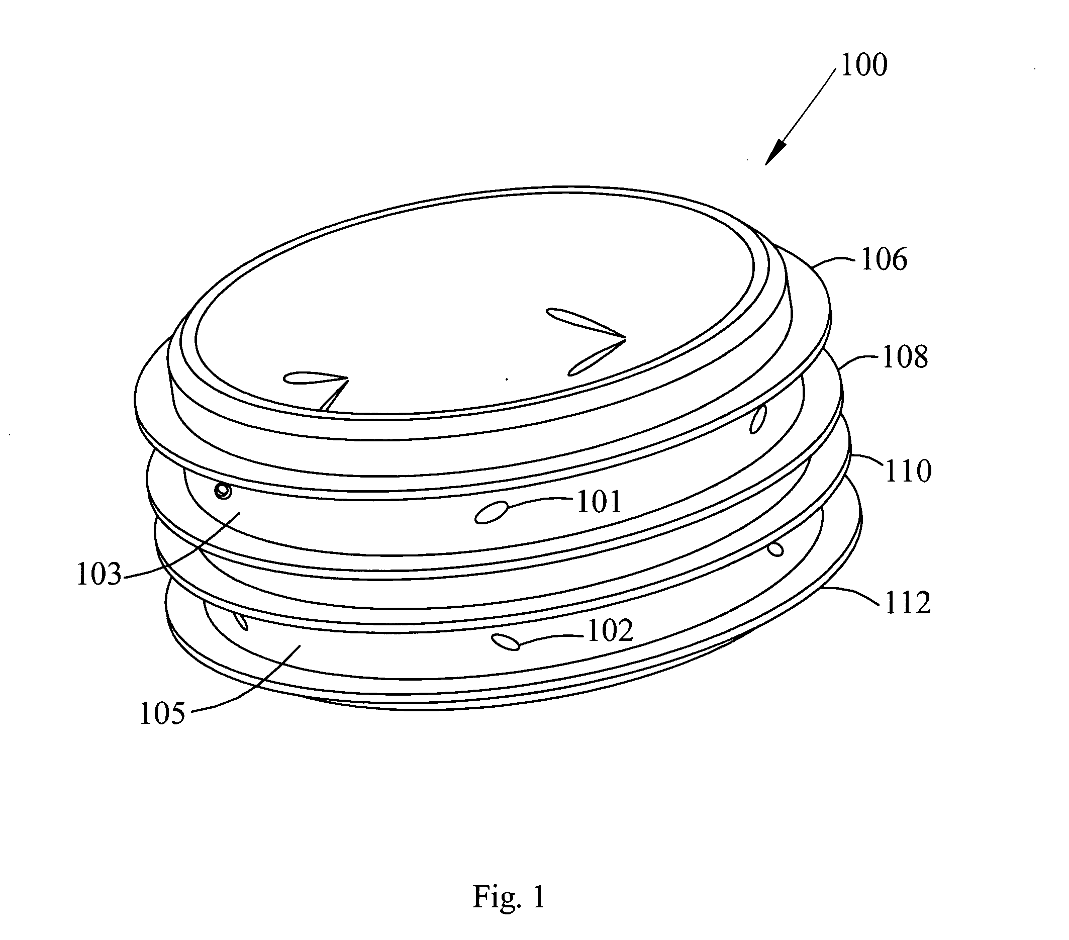
[0012] Referring now to the drawing wherein like numbers represent like parts in each of the several figures, FIG. 1 is a diagram of a vortex injector 100 with which the Sliding-Action Magneto-Mechanical Injector Throttling Device (SLAMMIT) may be used to improve the performance of the injector. The details of the structure and operation of such a vortex injector and its components such as fuel manifold 103, oxidizer manifold 105, representative fuel and oxidizer orifices 101 and 102, respectively, are found in U.S. Pat. No. 5,622,046, the disclosure text of which is fully incorporated herein by reference.

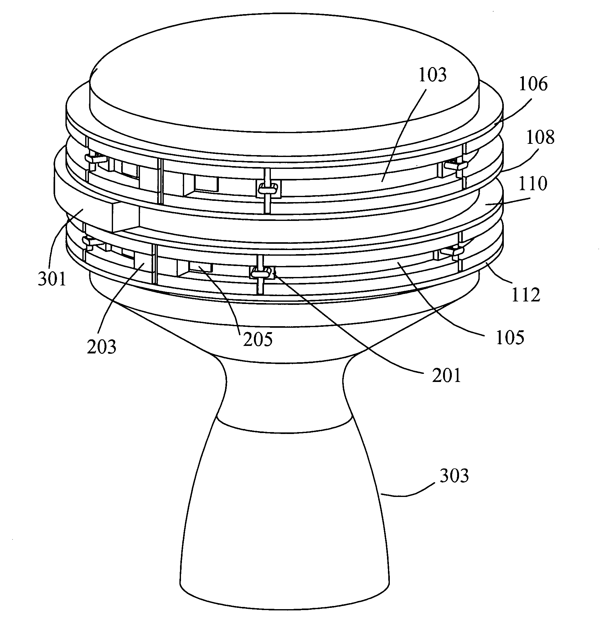
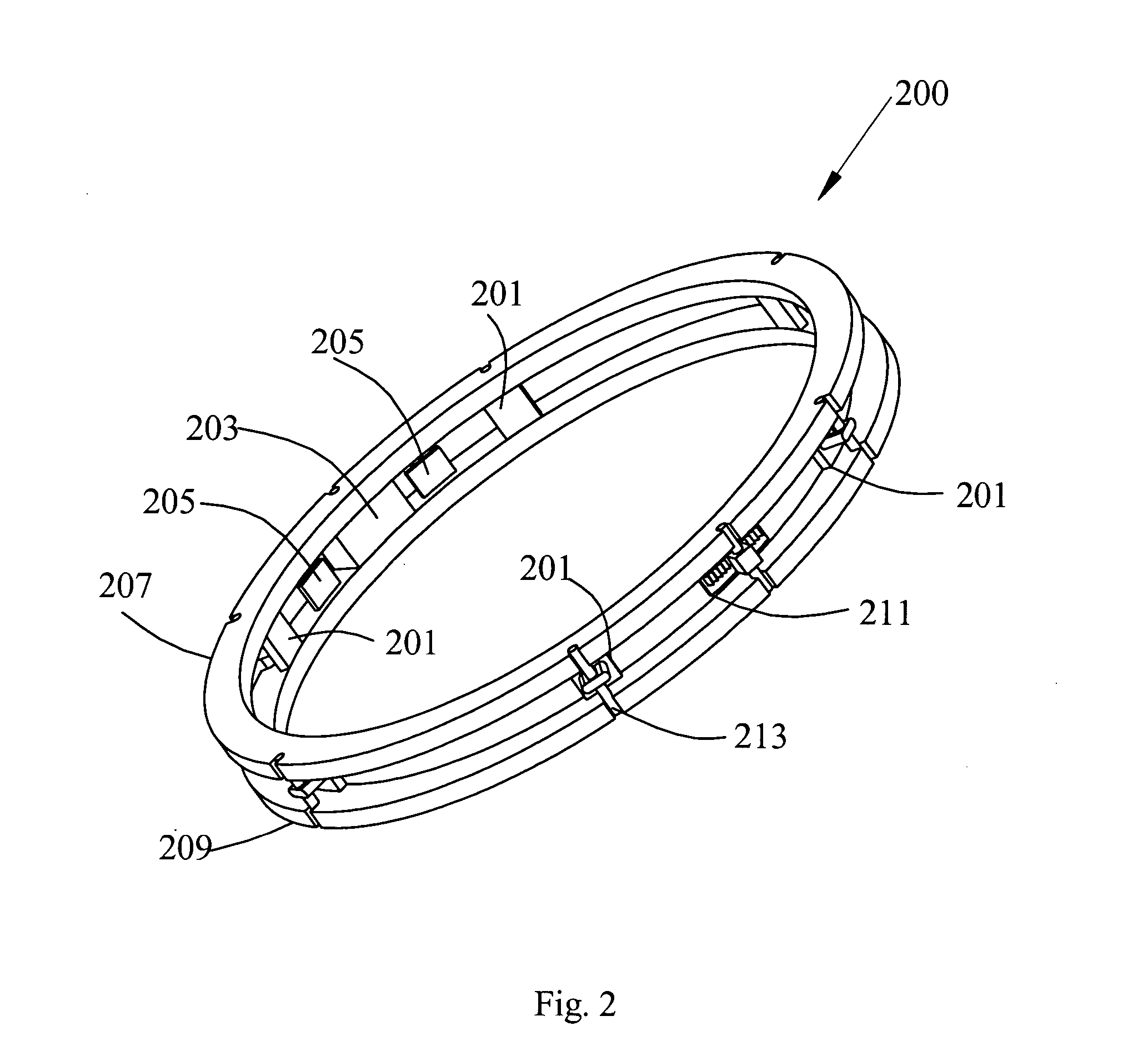
[0013]FIG. 2 illustrates a preferred embodiment of a SLAMMIT sub-assembly. Two such sub-assemblies along with electromagnet 301 between them comprise the SLAMMIT Device as depicted in FIG. 3 that also depicts nozzle throat 303 of the vortex thruster in which vortex injector 100 is employed.

[0014] As shown in FIG. 2, SLAMMIT sub-assembly 200 is comprised of first slide-guide ring ...


PUM


Abstract

Sliding-Action Magneto-Mechanical Injector Throttling Device (SLAMMIT) provides on-demand, yet accurate, throttling of the mass flow of the fuel and/or oxidizer into the combustion chamber of a vortex injector. At least two SLAMMIT sub-assemblies comprise the SLAMMIT Device and each sub-assembly is integrated into a manifold and is driven to slide in a given direction by a drive block that is internal to the sub-assembly. The drive block is, in turn, actuated by an electromagnet that is external to the SLAMMIT sub-assembly. As the SLAMMIT sub-assemblies slide, flappers inside the sub-assemblies achieve the effective opening size of the injection orifices anywhere between fully open and fully closed.

Description

DEDICATORY CLAUSE [0001] The invention described herein may be manufactured, used and licensed by or for the Government for governmental purposes without the payment to us of any royalties thereon.BACKGROUND OF THE INVENTION [0002] In a typical vortex injector used in conjunction with an engine in whose combustion chamber hypergolic ignition occurs, mass flow control is accomplished in one of two ways. One approach is to utilize throttling valves that are positioned outside of the fuel supply manifold such that the flow is regulated at a place other than the entrance to the injection orifices. This approach is simple to implement but high throttling ratios (maximum mass flow-rate divided by minimum mass flow-rate) cannot be achieved via this approach without significant losses in engine performance. The losses occur because the minimum allowed pressure drop across the injection orifices is not maintained at the entrance to the orifices. The only way to overcome these losses is to em...

Claims


Application Information

Patent Timeline
Patent Type & Authority Applications(United States)
IPC IPC(8): F02K9/52F02K9/56F02K9/60
CPCF02K9/52F02K9/60F02K9/56
Inventor MICHAELS, ROBERT S.ARSZMAN, JERROLD H.
Owner XILINX INC
Why Eureka
Try Eureka