Reducible support structures having off-axis engagement

a support structure and off-axis technology, applied in the direction of stand/trestle, mouthpiece/microphone attachment, kitchen equipment, etc., can solve the problems of not changing the height or length of the structure, not providing the user appropriate safety in operation, and the device may be bulky and take up more space than needed, etc., to achieve convenient transportation and storage of the structure in different applications, low profile and compact

a support structure and off-axis technology, applied in the direction of stand/trestle, mouthpiece/microphone attachment, kitchen equipment, etc., can solve the problems of not changing the height or length of the structure, not providing the user appropriate safety in operation, and the device may be bulky and take up more space than needed, etc., to achieve convenient transportation and storage of the structure in different applications, low profile and compact

US20050035247A1Inactive Publication Date: 2005-02-17ULTIMATE SUPPORT SYST

Image

  • Reducible support structures having off-axis engagement
  • Reducible support structures having off-axis engagement
  • Reducible support structures having off-axis engagement

Examples


Embodiment Construction

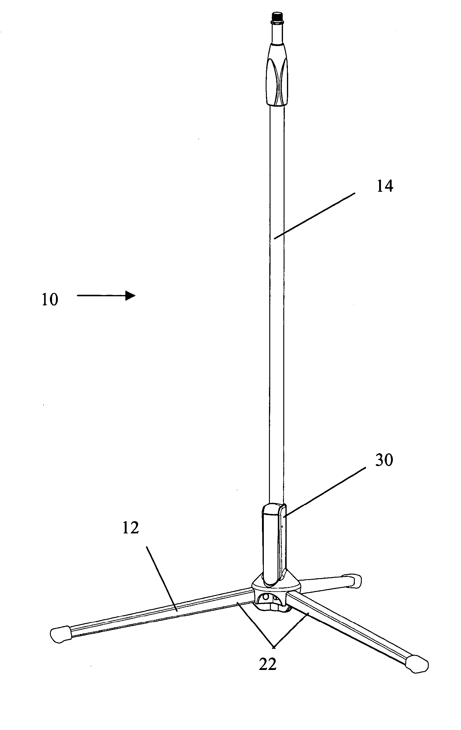
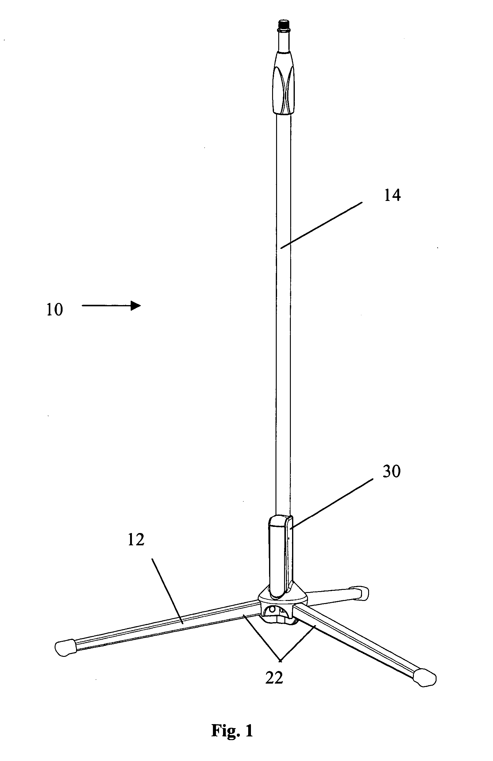
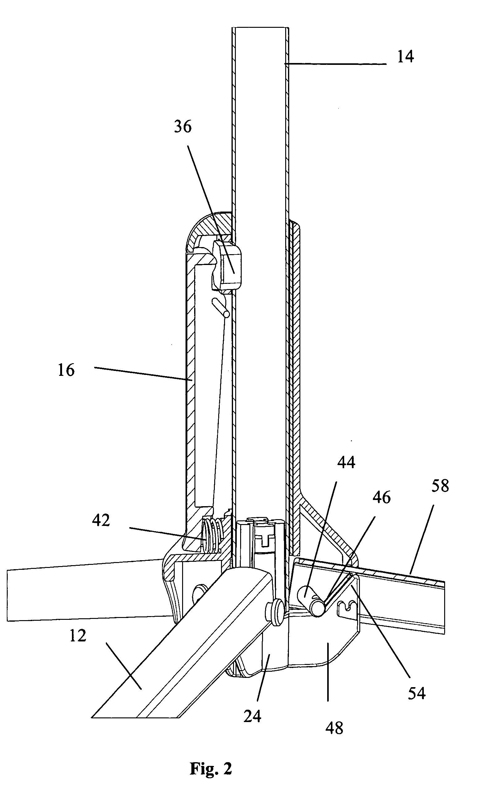
[0027] As can be understood from the discussion, the present invention may be embodied in a variety of ways. Although discussed in the context of a particular initial design, it should be understood that the various elements can be altered and even replaced or omitted to permit other designs and functionality as appropriate. Referring to the figures beginning with FIGS. 1, 9, and 10, it can be seen that in one sense the invention involves a reducible support structure (10). In some embodiments, there may be a first element, preferably an orthogonal element (14) provided and at least one limb (12) attached to a second element, preferably an operation element (16). The orthogonal element (14) may follow a longitudinal axis, where a longitudinal axis may follow some portion of the reducible support structure (10). The reducible support structure (10) need not be symmetrical about a longitudinal axis.

[0028] Further, an operation element (16) or a second element may be attached to the o...


PUM


Abstract

A reducible support system for supporting various items is presented in various embodiments. A reducible support structure, may comprise an operation element which may be attached to an orthogonal element. Limbs, such as a tripod, may be attached to the operation element and a plug element may provide a slide so that the limbs or tripod may open and collapse easily.

Description

[0001] This application is a continuation-in-part of application Ser. No. 10 / 342,668 filed Jan. 14, 2003, now U.S. Pat. No. 6,789,772.FIELD [0002] This invention relates generally to the field of reducible support structures. Specifically, it relates to reducible support structures used with various stands which may be especially applicable to bicycle items, music items, illumination items, and particularly, to microphone stands. More specifically, the invention may relate to a reducible tripod base that may be easily collapsed and expanded using an off-axis relationship. BACKGROUND [0003] Collapsible stand devices have historically taken many forms dependent upon, generally, the user having to place their hand on the device where the user's hand may get trapped or pinched as the device may be being collapsed or opened. Traditional forms of collapsible stands and support systems may have incorporated many fields, such as tripods and easels, or the like. [0004] One particular field i...

Claims


Application Information

Patent Timeline
17 Feb 2005
Publication
US20050035247A1
IPC
F16M11/16; H04R1/08
CPC
F16M11/16; F16M2200/027; F16M11/245; H04R1/08
Inventors
ROBERTS, WALTON DAVID; EASON, DONALD H.