Arrangement of components in a fluid energy machine and assembly method

a technology of fluid energy machines and components, applied in mechanical equipment, machines/engines, liquid fuel engines, etc., can solve problems such as harboring the risk of damage, damage to adjacent components, and damage to adjacent parts

Inactive Publication Date: 2017-02-02
SIEMENS AG
View PDF0 Cites 6 Cited by
  • Summary
  • Abstract
  • Description
  • Claims
  • Application Information

AI Technical Summary

Benefits of technology

[0038]This axial securing of at least one mounting sleeve, advantageously of both mounting sleeves, permits the axial securing, already discussed above, of the cover, which is advantageously arranged axially loosely on the low-pressure insert and by means of which the first mounting sleeve can be secured axially.

Problems solved by technology

Here, damage can be caused to adjacent components, for example to the corresponding cover seals or to the shaft seals, or damage can be caused in the event of an offset of the rotor relative to the static components—that is to say the stator—of said transportable unit.
Furthermore, said assembly must subsequently be rotated into the operating position again, which likewise harbors the risk of damage and necessitates a reorientation of the housing.
Such an apparatus has only a limited load capacity and is therefore suitable only for machines up to a particular structural size.

Method used


Image

  • Arrangement of components in a fluid energy machine and assembly method
  • Arrangement of components in a fluid energy machine and assembly method
  • Arrangement of components in a fluid energy machine and assembly method

Examples


Embodiment Construction

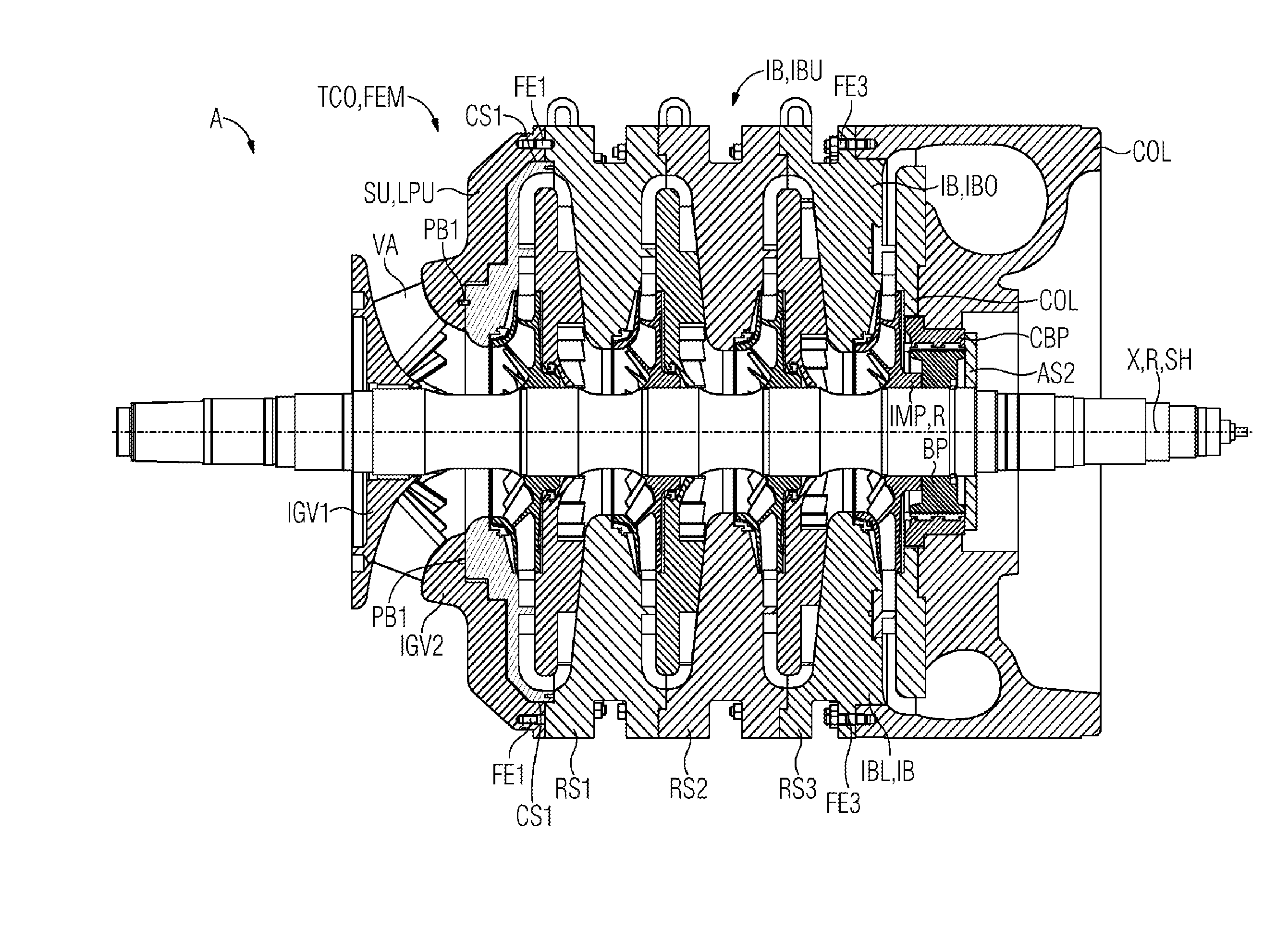
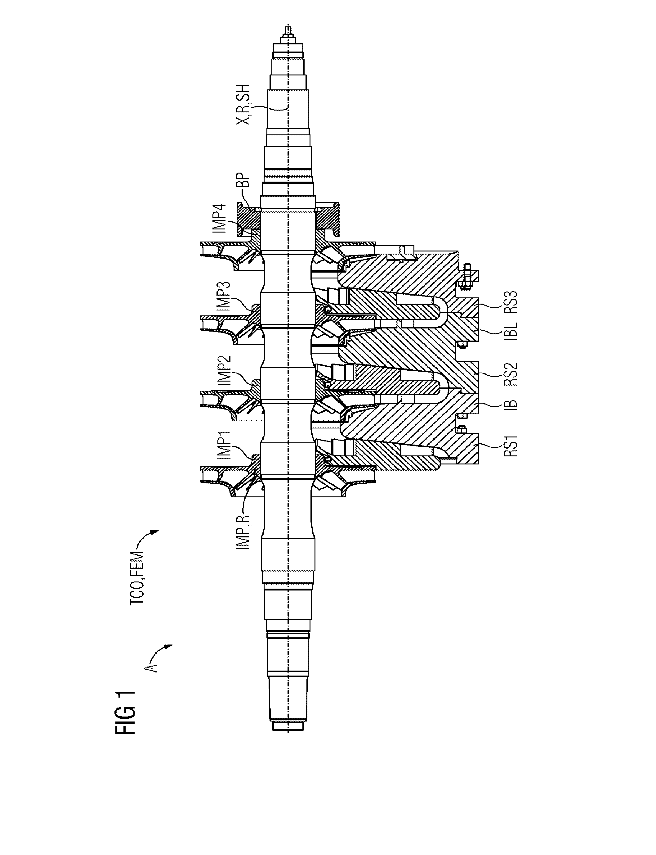
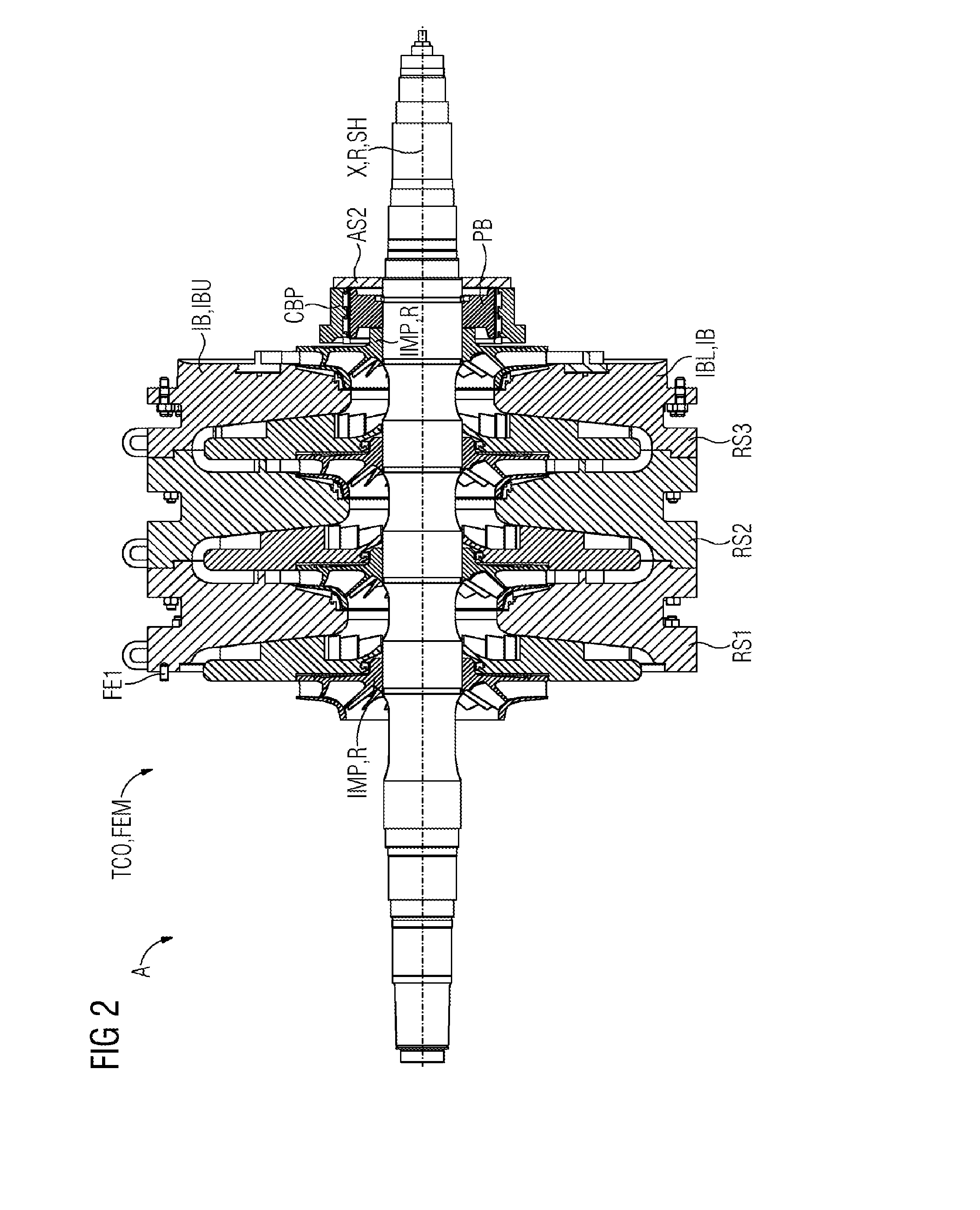
[0041]All directional statements such as axial, radial, tangential or circumferential direction always relate—unless stated otherwise—to the longitudinal axis X of the rotor. The longitudinal axis X of the rotor R corresponds to the axis of rotation of the rotor R during operation. The central longitudinal axes of the impellers, of the inner bundle IB, of an outer housing OC, of a cover COV, of a low-pressure insert LPU and of a collector COL run in substantially coincident fashion, aside from planned or unplanned deviations which are not relevant in the context of the invention.

[0042]FIGS. 1-5 show, in each case in an illustration of a longitudinal section, an arrangement A comprising components of a fluid energy machine FEM, specifically of a turbocompressor TCO, with a longitudinal axis X. Here, FIGS. 1-5 show different stages of the assembly of the components in the context of an assembly process in successive steps, wherein FIG. 1 illustrates the smallest number of components a...


PUM


Abstract

An assembly method and an arrangement of components in a fluid energy machine, in particular a turbocompressor, with a longitudinal axis. The arrangement includes: an inner bundle to be arranged in an outer casing of the fluid energy machine, a low-pressure unit of the fluid energy machine, at least one cover of the fluid energy machine for the axial end-side closure of the outer casing on at least one end side, wherein these components are arranged axially adjacent to one another in the sequence cover, low-pressure unit, inner bundle and the cover is releasably attached to the low-pressure unit and the inner bundle is releasably attached to the low-pressure unit such that there results a transportable unit.

Description

CROSS REFERENCE TO RELATED APPLICATIONS[0001]This application is the US National Stage of International Application No. PCT / EP2015 / 058412 filed Apr. 17, 2015, and claims the benefit thereof. The International Application claims the benefit of German Application No. DE 102014207461.4 filed Apr. 17, 2014. All of the applications are incorporated by reference herein in their entirety.FIELD OF INVENTION[0002]The invention relates to an arrangement of components of a fluid energy machine, in particular of a turbocompressor, with a longitudinal axis, comprising an inner bundle for arrangement in an outer housing, a low-pressure insert, and at least one cover for the axial face-side closure of the outer housing at at least one face side.BACKGROUND OF INVENTION[0003]Such fluid energy machines or arrangements of the type mentioned in the introduction are already known from, for example, EP 2 024 646 B1 or EP 1 952 030 B1. The latter document also describes an assembly method for a turbocompr...

Claims


Application Information

Patent Timeline
Patent Type & Authority Applications(United States)
IPC IPC(8): F04D29/62F04D29/44F04D29/42F04D1/06F04D17/08
CPCF04D29/628F04D1/06F04D17/08F04D29/448F04D29/4206F04D29/426F04D29/444F04D29/624F01D25/285F04D17/122F05D2260/02F01D25/28
Inventor HUTH, SEBASTIANNADIETER
Owner SIEMENS AG
Why Eureka
Try Eureka