Eureka AIR delivers breakthrough ideas for toughest innovation challenges, trusted by R&D personnel around the world.

Magnetic field coupling-eliminating magnetic bearing and manufacturing method thereof

A technology for magnetic bearings and magnetic field elimination, applied in the direction of magnetic bearings, bearings, bearing components, etc., can solve the problems of difficult guarantee, complicated manufacturing process, high concentricity, etc., and achieve the goal of improving control accuracy, simple manufacturing process, and reducing control difficulty Effect

Inactive Publication Date: 2009-07-15
WUHAN UNIV OF TECH
View PDF1 Cites 7 Cited by
  • Summary
  • Abstract
  • Description
  • Claims
  • Application Information

AI Technical Summary

Problems solved by technology

[0004] The Chinese patent "Electromagnetic Bearing Without Magnetic Field Coupling" (Notice No. CN2783023) is a utility model patent, which realizes magnetic field-free coupling between electromagnets and between electromagnets and bearing housings in principle, but does not specifically propose its manufacture. Method and process
Due to the problem of structure, the defect of this electromagnetic bearing is: the announced magnet iron core is a "C" shaped structure, and the feasibility of a magnetic bearing without magnetic field coupling is only proposed in principle, and its specific manufacturing process and assembly are not proposed. , such as how to ensure the concentricity of its four magnet cores, etc.
The defects in the manufacturing process of the bearing are: first, its concentricity is guaranteed by the fixture, and its concentricity is limited by the precision of the fixture; second, there is over-position in the assembly process; Concentricity

Method used


Image

  • Magnetic field coupling-eliminating magnetic bearing and manufacturing method thereof
  • Magnetic field coupling-eliminating magnetic bearing and manufacturing method thereof
  • Magnetic field coupling-eliminating magnetic bearing and manufacturing method thereof

Examples


Embodiment Construction

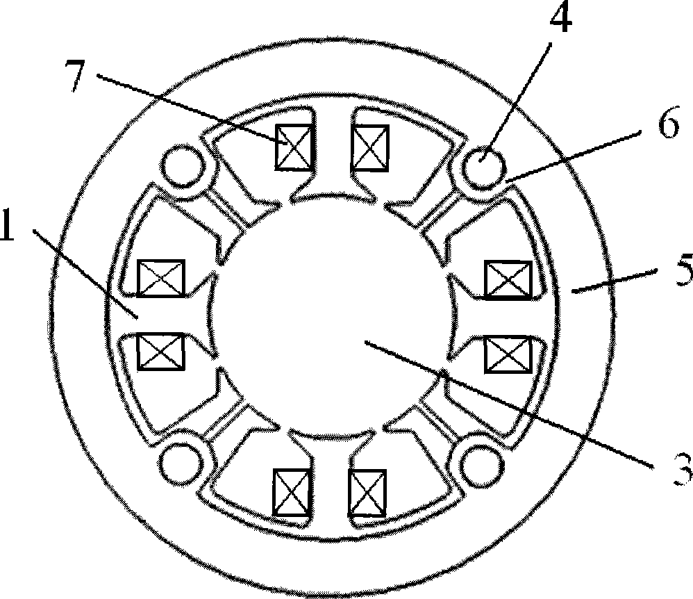
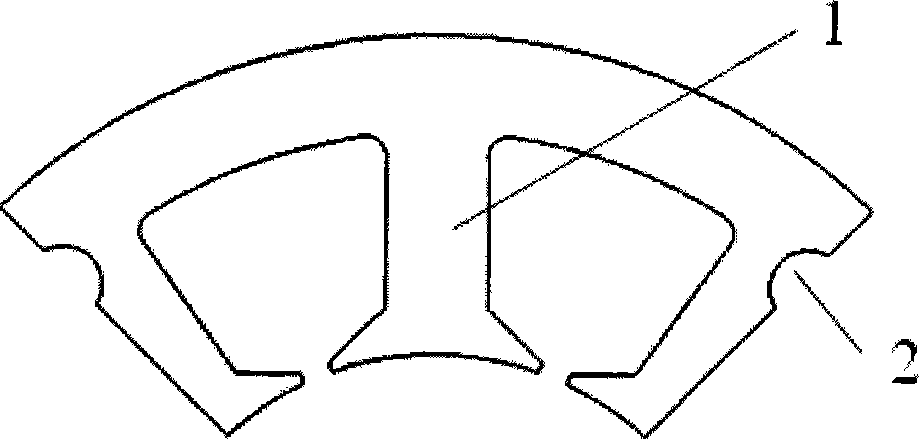
[0021] The magnetic force bearing that eliminates magnetic field coupling provided by the present invention has a structure such as figure 1 As shown: it is composed of four magnet cores 1, four coils 7, two magnetic isolation rings 5, and four rivets 4, and the four magnet cores 1 are all "E"-shaped structures. Among them: the two magnetic isolation rings are matched with the outer circle of the magnet core by using their spigots, and are respectively placed on both sides of the magnet core to clamp the magnet core, and the magnetic isolation ring and the magnet core are riveted together by rivets, each A coil 7 is wound with an enameled wire on the magnet core to form a whole magnetic bearing.

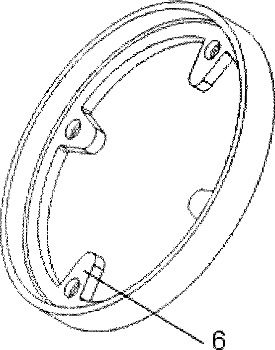
[0022] Described magnetic isolation ring 5 has a structure such as figure 2 As shown: four lugs 6 are evenly distributed on its inner circle, and each lug 6 has a round hole for rivet connection; Round fit spigot structure.

[0023] The magnetic isolation ring 5 and the rivet 4 c...


PUM


Abstract

The invention relates to a magnetic bearing used for eliminating magnetic field coupling. The magnetic bearing consists of four magnet cores (1), four coils (7), two magnet isolating rings (5) and four rivets (4). The two magnet isolating rings are matched with the outer circles of the magnet cores by spigots of the magnet isolating rings and are respectively arranged at two sides of the magnet cores to clamp the magnet cores. The magnet isolating rings and the magnet cores are riveted as a whole by the rivets (4). The four magnet cores are respectively winded with a coil (7) to form the whole magnetic bearing. The four magnet cores of the magnetic bearing consist of a plurality of silicon steel sheets which are coincided and are all structured as character E, both two ends of each silicon steel sheet are provided with semicircular slots (2), and the rivets (4) restrain the circumferential position between each silicon steel sheet by the semicircular slots. The magnetic bearing adopts four magnet cores and four coils which are riveted as a whole by the magnet isolating rings made of non magnetic conduction material and the rivets, and each magnet core does not contact with each other, thereby eliminating the magnetic field coupling of the magnetic bearing.

Description

technical field [0001] The invention relates to the field of bearings, in particular to a magnetic bearing for eliminating magnetic field coupling and a manufacturing method thereof. Background technique [0002] Magnetic bearing is a new type of high-performance bearing that uses electromagnetic force to suspend the rotor in space and realize non-contact support between the rotor and the stator. Compared with ordinary bearings, magnetic bearings mainly have the advantages of no contact, no lubrication, and the ability to control the rotor position. [0003] In order to improve the performance of the magnetic bearing, it is necessary to eliminate the magnetic field coupling. After searching, there are following patent documents at present. [0004] The Chinese patent "Electromagnetic Bearing Without Magnetic Field Coupling" (Notice No. CN2783023) is a utility model patent, which realizes magnetic field-free coupling between electromagnets and between electromagnets and bea...

Claims


Application Information

Patent Timeline
IPC IPC(8): F16C32/04
CPCF16C32/0461F16C32/048F16C43/00
Inventor 胡业发王晓光吴华春
Owner WUHAN UNIV OF TECH
Why Eureka
Eureka Blog
Learn More