Projector mount

a projector and mount technology, applied in the field of projector mounts, can solve the problems of relatively high cost of locking devices, and achieve the effect of improving security and facilitating the adjustment of the distance between the projector and the screen

Inactive Publication Date: 2005-02-17
TEMPUS COMP
View PDF0 Cites 61 Cited by
  • Summary
  • Abstract
  • Description
  • Claims
  • Application Information

AI Technical Summary

Benefits of technology

[0005] An object of the present invention is to provide an improved projector mount, and in particular facilities that allows rapid detachment of a projector, for use either conventionally or on part of another mount; while at the same time affording improved security. A further object of the invention is to

Problems solved by technology

It also means that only one lock is required when the projector is being used in several locations; this f

Method used


Image

  • Projector mount
  • Projector mount
  • Projector mount

Examples


Embodiment Construction

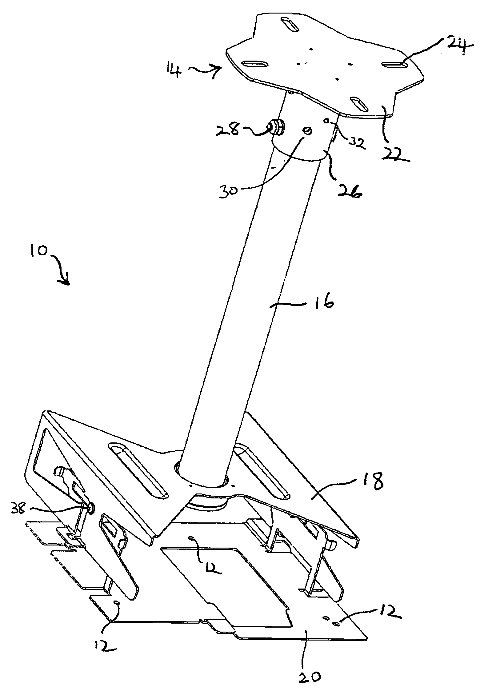
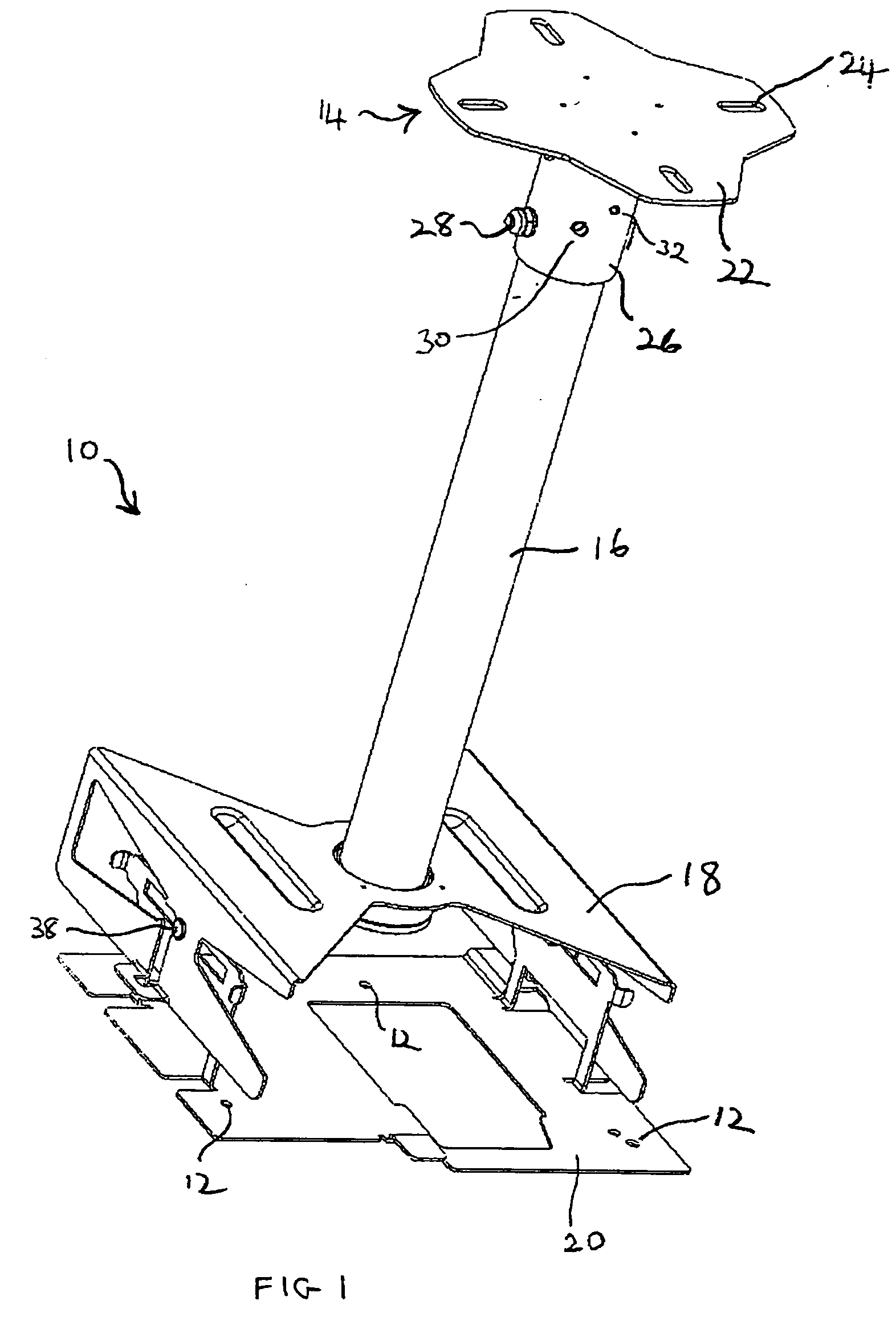
[0021] A first embodiment of the invention will now be described by reference to FIGS. 1 to 4. Referring to FIG. 1; the projector ceiling mount 10 comprises a ceiling fixing plate 14, a pole 16, an engagement element 18; and a projector mounting plate 20.

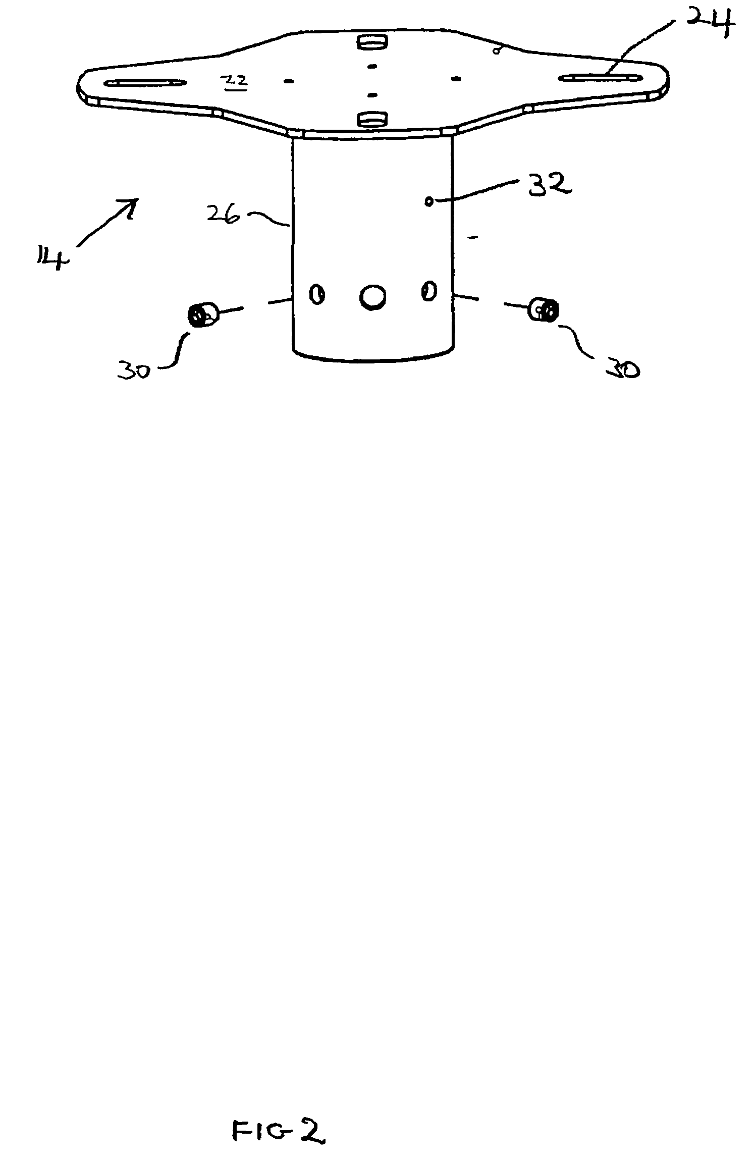
[0022] The ceiling fixing plate 14 (see FIG. 2) comprises a central portion from which four arms 22 radiate; each arm having a slot 24 through which a bolt or screw may pass to fix the plate to a ceiling. A central tubular sleeve 26 depends downwardly from the central portion of plate 14 and houses the upper end of mounting pole 16. The upper end of pole 16 is secured within sleeve 26 by means of a nut and bolt 28 that passes through circular holes located diametrically on both the pole 16 and the sleeve 26. A pair of threaded grub screws 30 are located in threaded bores within sleeve 26 in order to allow the pole to be held in place, by tightening the screws 30, prior to securing using bolt 28. As supplied for assembly, a pair of ...


PUM


Abstract

A projector ceiling mount comprising a support member adapted for attachment to the ceiling and a detachable member adapted for attachment to a projector and engagement means that allow the detachable member to be readily attached and locked to the support member and adjustment means that, in use, allow the horizontal position and tilt of a mounted projector to varied with respect to the mount.

Description

BACKGROUND OF THE INVENTION [0001] This invention relates to projector mounts and in particular to mounts designed for attachment to ceilings. [0002] Interactive white-board systems are being increasingly used for teaching, lecturing etc.. Such systems typically comprise a white board mounted to a wall of a room and a LCD projector mounted to the room ceiling. The LCD projector in particular is expensive. When used in educational establishments such projectors are particularly vulnerable to theft. The high cost of LCD projectors also provides an incentive for a single projector to be shared by users in a number of separate rooms. Movement of a projector from one room to another presents raises additional security issues. [0003] Projector mounts are known where the projector is bolted to a detachable member of a mount. On occasions it may be desirable to use to a projector bolted to such a detachable member on a work top or the like. Known projector mounting systems do not readily al...

Claims


Application Information

Patent Timeline
IPC IPC(8): F16M11/04F16M11/12G03B21/00H04N5/74
CPCF16M11/04F16M11/041F16M11/10H04N9/3141F16M13/02G03B21/00F16M11/12G03B21/006
Inventor RIXOM, CHRISTOPHER PAUL
Owner TEMPUS COMP
Why Eureka
Try Eureka