Sensor

a sensor and sensor technology, applied in the field of sensors, can solve the problem of not being able to detect objects entering protected zones, and achieve the effect of simplifying the sensor structure and reducing the number of sensor parts

Active Publication Date: 2005-02-17
OPTEX CO LTD
View PDF2 Cites 18 Cited by
  • Summary
  • Abstract
  • Description
  • Claims
  • Application Information

AI Technical Summary

Benefits of technology

[0015] Alternatively or in addition thereto, at least one of the optical path varying means may be such that one or more rotatable shafts for rotating at least one of the light-projecting component or components and at least one of the light-receiving component or components is or are disposed between at least one of the light-projecting component or components and at least one of the light-receiving component or components; and when carrying out detection with respect to at least one distant zone, at least one of the light-projecting component or components and / or at least one of the light-receiving component or components is or are rotated in at least one direction such as would tend to increase the degree to which at least one of the light-projecting surface or surfaces faces at least one of the light-receiving surface or surfaces.
[0016] Adoption of the foregoing specific optical path varying means constitution(s) makes it possible to eliminate the need to provide additional member(s) that might be arranged therein only with difficulty. As a result, it is possible to reduce sensor parts count and / or simplify sensor structure.

Problems solved by technology

For this reason, while it is possible with this automatic door sensor to vary protected zones so as to form arbitrary protected zones (first zone(s) and second zone(s)), it is not possible to carry out detection of objects entering protected zones such that equivalent light density, i.e., optical sensitivity, is used for detection thereof across all protected zones.

Method used


Image

  • Sensor
  • Sensor
  • Sensor

Examples


first embodiment

[0022] First Embodiment

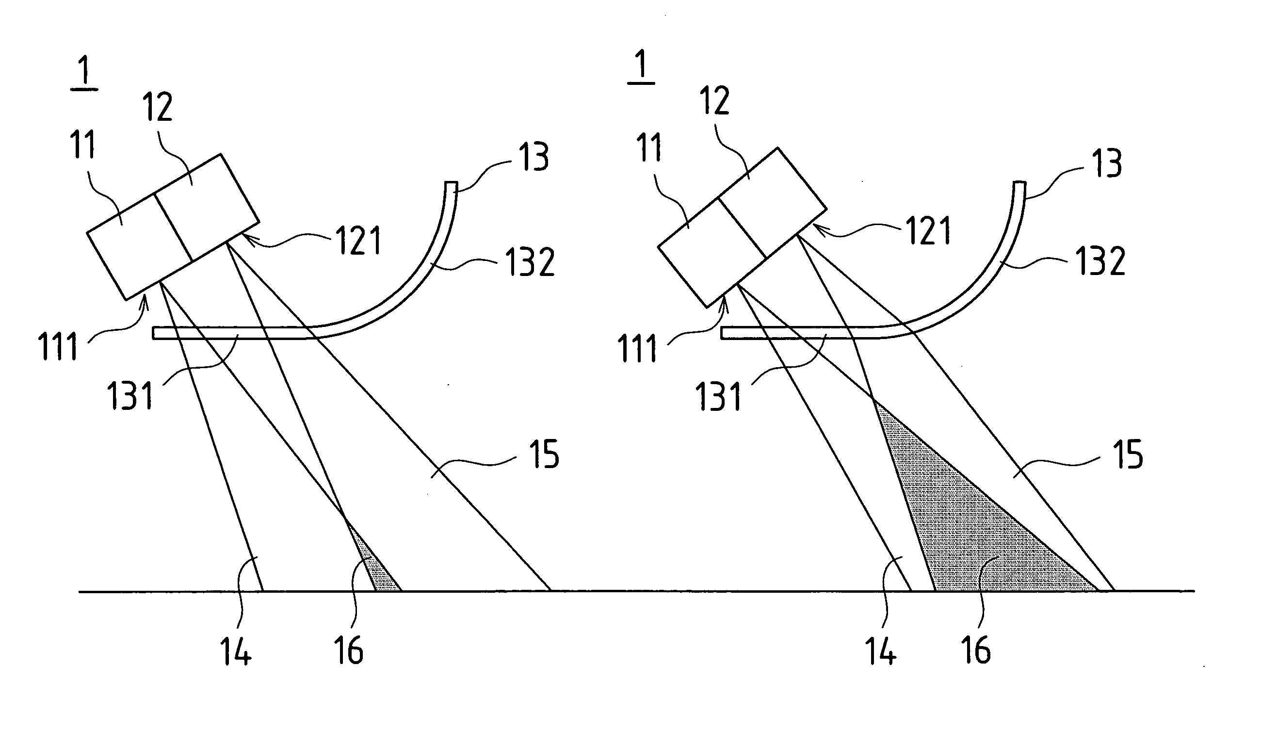
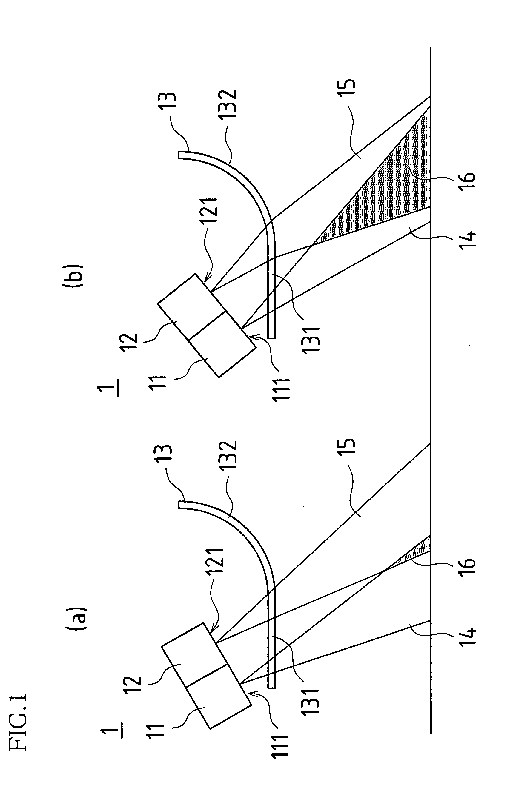
[0023] As shown in FIG. 1, automatic door sensor 1 is such that light-projecting component(s) 11, irradiating light from light-projecting surface(s) 111; and light-receiving component(s) 12, receiving light irradiated from such light-projecting component(s) 11, the received light being incident on light-receiving surface(s) 121 after having been reflected, are arrayed vertically at the time that this automatic door sensor 1 is installed. Furthermore, at this automatic door sensor 1, cover(s) is / are employed at housing surface(s) facing light-projecting and light-receiving surfaces 111, 121 for allowing light to be irradiated from light-projecting component 11 and incident on light-receiving component 12. Note also that detection conditions are such that constant density is maintained in the light irradiated from light-projecting surface 111 of light-projecting component 11.

[0024] In accordance with such constitution, this automatic door sensor 1 is such that ...

second embodiment

[0041] Second Embodiment

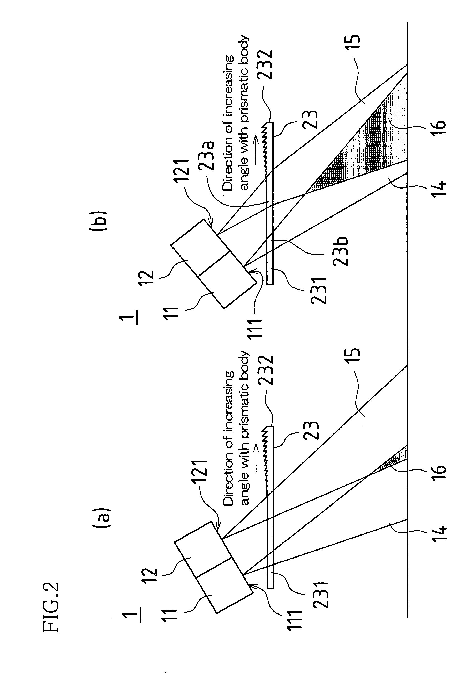
[0042] The automatic door sensor of the second embodiment differs from the automatic door sensor of the foregoing first embodiment only with respect to the optical path varying means, the constitutions thereof being identical in other respects. Description of the present second embodiment will therefore be confined to the optical path varying means with respect to which it differs from the automatic door sensor of the first embodiment, and like constituents will be assigned like reference numerals and description thereof will be omitted.

[0043] As shown in FIG. 2, arranged at automatic door sensor 1 there are light-projecting component 11 and light-receiving component 12, cover(s) being employed at housing surface(s) facing light-projecting and light-receiving surfaces 111, 121 of these light-projecting and light-receiving components 11, 12. Note also that detection conditions are such that constant density is maintained in the light irradiated from light-pro...

third embodiment

[0051] Third Embodiment

[0052] The automatic door sensor of the third embodiment differs from the automatic door sensor of the foregoing first embodiment only with respect to the optical path varying means, the constitutions thereof being identical in other respects. Description of the present third embodiment will therefore be confined to the optical path varying means with respect to which it differs from the automatic door sensor of the first embodiment, and like constituents will be assigned like reference numerals and description thereof will be omitted.

[0053] As shown in FIG. 3, arranged at automatic door sensor 1 there are light-projecting component 11 and light-receiving component 12. Note also that detection conditions are such that constant density is maintained in the light irradiated from light-projecting surface 111 of light-projecting component 11.

[0054] Furthermore, such automatic door sensor 1 may be provided with optical path varying means varying projected light o...


PUM


Abstract

Sensor(s) may be such that light-projecting component(s) and light-receiving component(s) are arranged therein. Furthermore, such sensor(s) may be provided with optical path varying means varying projected light optical path(s) and/or received light optical path(s) so as to physically vary overlapping zone(s). Such optical path varying means may carry out adjustment of optical sensitivity by increasing extent(s) of overlapping zone(s) when carrying out detection with respect to zone(s) distant from such sensor(s) and/or decreasing extent(s) of overlapping zone(s) when carrying out detection with respect to zone(s) proximate to such sensor(s).

Description

BACKGROUND OF INVENTION [0001] This Nonprovisional application claims priority under 35 U.S.C. § 119(a) on patent Application No. 2002-333704 filed in Japan on Nov. 18, 2002, the entire contents of which are hereby incorporated by reference. [0002] The present invention pertains to a sensor detecting entry of object(s) into overlapping zone(s) at which projected light optical path(s) of light irradiated from light-projecting component(s) overlap received light optical path(s) of light incident on light-receiving component(s). [0003] Conventional sensors include automatic door sensors having the ability to vary the protected zone for detection of persons traveling therethrough, as disclosed for example at Japanese Patent Application Publication Kokai No. H3-55381 (1991). [0004] In this automatic door sensor, a light-projecting component and a light-receiving component are disposed above an automatic door. A two-piece rotatable mirror is employed as reflecting mirror to reflect light ...

Claims


Application Information

Patent Timeline
Patent Type & Authority Applications(United States)
IPC IPC(8): G01V8/14G01J1/02G01J1/06G01V8/10G01V8/12
CPCG01V8/10
Inventor MATSUYAMA, TOSHIYASUFUKUDA, KIYOFUMITAKADA, YASUHIRO
Owner OPTEX CO LTD
Why Eureka
Try Eureka