Solid-state camera device and method of manufacturing the same, and method of making mask for manufacturing the device

a camera device and solid-state technology, applied in the field of solid-state camera devices and methods of manufacturing the same, and the method of making masks for manufacturing the devices, can solve the problem that the shading correction technique of the light-scaling technique cannot be sufficiently corrected

Inactive Publication Date: 2005-02-17
SHARP KK
View PDF6 Cites 23 Cited by
  • Summary
  • Abstract
  • Description
  • Claims
  • Application Information

AI Technical Summary

Problems solved by technology

The slight-scaling technique can not sufficiently

Method used


Image

  • Solid-state camera device and method of manufacturing the same, and method of making mask for manufacturing the device
  • Solid-state camera device and method of manufacturing the same, and method of making mask for manufacturing the device
  • Solid-state camera device and method of manufacturing the same, and method of making mask for manufacturing the device

Examples


example 1

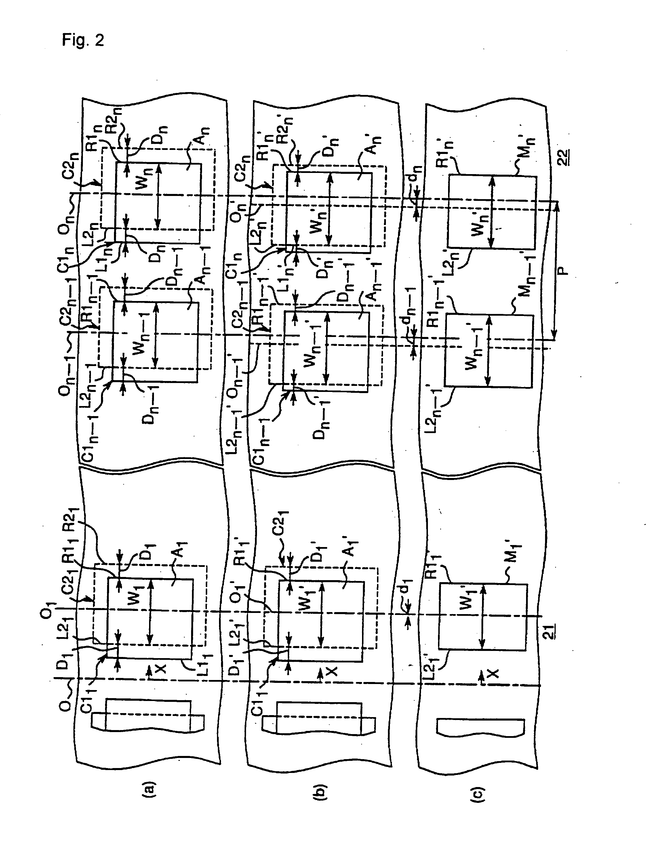
FIG. 2 explains an example in which the method of manufacturing a mask according to the present invention is applied in the lateral direction (X-direction). Specifically, FIGS. 2(a), (b) and (c) illustrate one line of a pattern (mask patterning data) in the lateral direction from the middle of the camera region 21 to the peripheral camera region 22 (right end), respectively, wherein the X-coordinate of the center of the camera region O is defined to be 0. Additionally, the left part of the pattern is not illustrated in the figure because the mask pattern is symmetrical.

Step 1

First, the first mask patterning data and the second mask patterning data are prepared at respective minimum size units as usual (e.g., 0.01 μm) to define, in the first data, a plurality of rectangular regions, C11, . . . , C1n−1, C1n (represented by solid lines; hereinafter, referred to as “first rectangular region”) aligning in a line at a constant interval P in the lateral direction and, in the second dat...

example 2

Next, FIGS. 3 through 5 explain another example in which the method of manufacturing a mask according to the present invention is applied both in the lateral direction (X-direction) and in the longitudinal direction (Y-direction). More particularly, FIGS. 3 through 5 illustrate a pattern (mask patterning data) of a one-fourth part of the whole camera region including the middle of the camera region 21 and the peripheral camera region 22 (right end, upper end), wherein the X- and Y-coordinates of the center of the camera region O is defined to be (0, 0). Additionally, a pattern of the remaining three-fourth part is omitted because the mask pattern is symmetrical.

Step 1

First, the first mask patterning data and the second mask patterning data are prepared at respective minimum size units as usual (e.g., 0.01 μm) to define, in the first data, a plurality of rectangular regions, C111, . . . , C1n(n−1), C1nn (represented by solid lines; hereinafter, referred to as “first rectangular ...


PUM


Abstract

The present invention provides a solid-state camera device which can improve both the shading caused by the eclipse of the incident light and the shading cased by the rim darkening. The present solid-state camera device comprises a plurality of light-receiving parts 1 arranged at a constant interval on a substrate, and a plurality of light-focusing parts 2 disposed corresponding to each of the light-receiving parts on the substrate surface so that the incident light is focused on the light-receiving parts. Further, the position of each of the light-focusing parts is shifted gradually larger toward the center of the camera region O based on the corresponding light-receiving parts and the size along the substrate surface of each of the light-focusing parts 2, W1′, . . . , Wn−1′, Wn′, becomes gradually larger, as the location of the light-focusing parts is getting closer to the peripheral camera region 22 from the middle of the camera region 21 in front of the exit pupil on the substrate in the direction along the substrate surface.

Description

FIELD OF THE INVENTION The present invention relates to a solid-state camera device which can correct shading, and to a method of manufacturing the same. The present invention also relates to a method of manufacturing a mask for forming light-receiving parts of such a solid-state camera device. BACKGROUND OF THE INVENTION Recently, solid-state camera devices are built in many video cameras and electronic still cameras in order to reduce size and weight of such cameras. As shown in FIG. 6, a solid-state camera device, generally, comprises a plurality of sets of a light-receiving part 1 and a vertical transfer part 6 which are arranged along by each other on a semi-conductor substrate 7, a plurality of vertical transfer electrodes 5 which are formed on each of the vertical transfer parts 6, a shading film 4 which covers the vertical transfer parts 6 and opens on the light-receiving parts 1, and a plurality of color filters 3 which are arranged above each of the light-receiving parts...

Claims


Application Information

Patent Timeline
IPC IPC(8): G03F1/00G03F1/68G03F1/78H01L21/027H01L27/14H01L27/146H01L27/148H04N5/335H04N5/357H04N5/361H04N5/369H04N5/372
CPCH01L27/14627H01L27/146
Inventor KAMIMURA, SHINYAINOUE, MASASHI
Owner SHARP KK
Why Eureka
Try Eureka