Magnetic discrete track recording disk

a discrete track and magnetic technology, applied in the field of disk drives, can solve problems such as not having a desired “

Inactive Publication Date: 2005-02-17
KOMAG
View PDF33 Cites 123 Cited by
  • Summary
  • Abstract
  • Description
  • Claims
  • Application Information

AI Technical Summary

Problems solved by technology

Also, because the track widths are very small, any misregistration of a track (e.g., thermal expansion) may affect the writing and / or reading with the head by an adjacent track.
One problem with prior DTR magnetic recording disks is that they may not have a desired “preferred” circumferential orientation of magnetic material in their magnetic recording films.

Method used


Image

  • Magnetic discrete track recording disk
  • Magnetic discrete track recording disk
  • Magnetic discrete track recording disk

Examples


Embodiment Construction

[0018] In the following description, numerous specific details are set forth such as examples of specific materials or components in order to provide a thorough understanding of the present invention. It will be apparent, however, to one skilled in the art that these specific details need not be employed to practice the invention. In other instances, well known components or methods have not been described in detail in order to avoid unnecessarily obscuring the present invention.

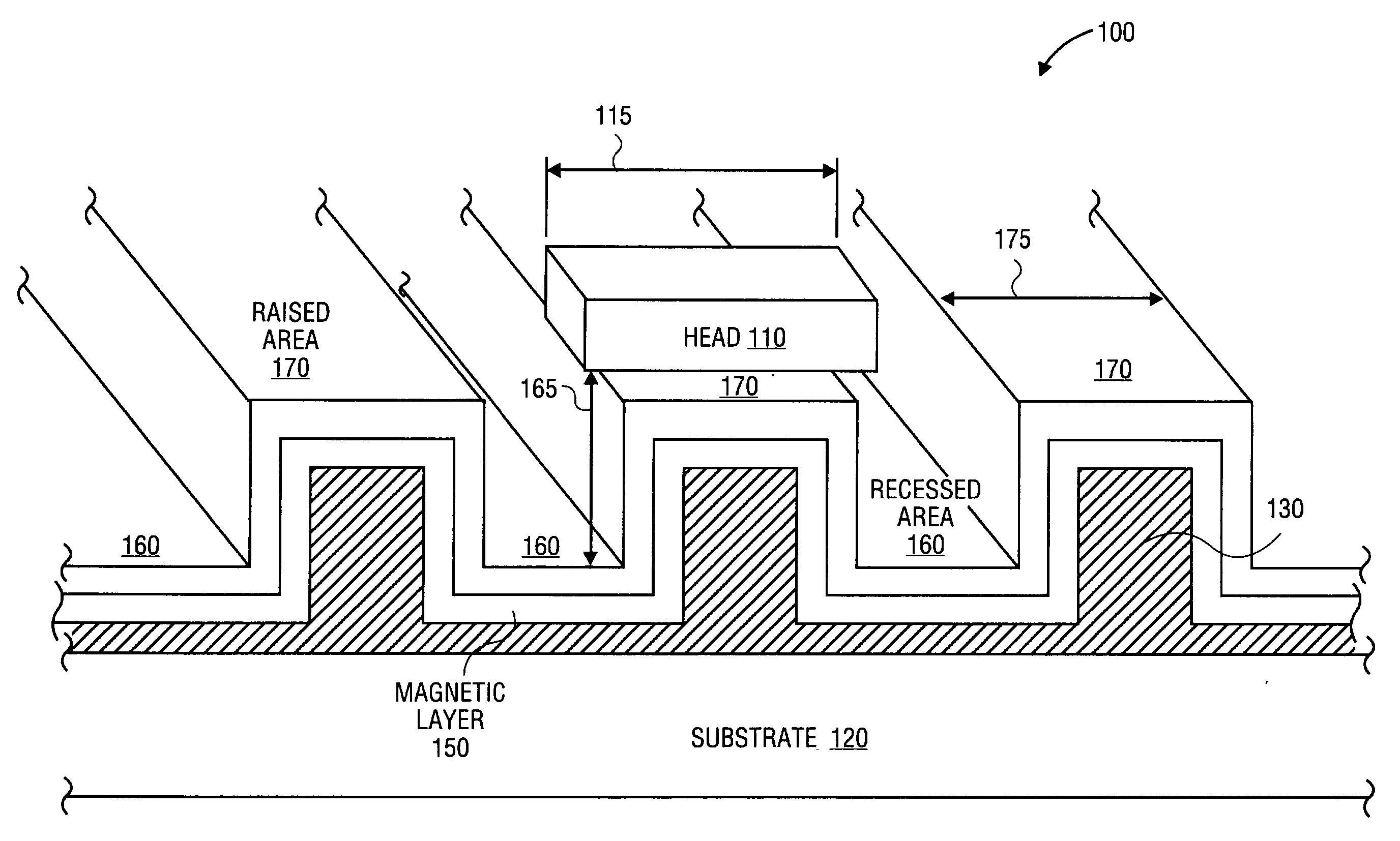
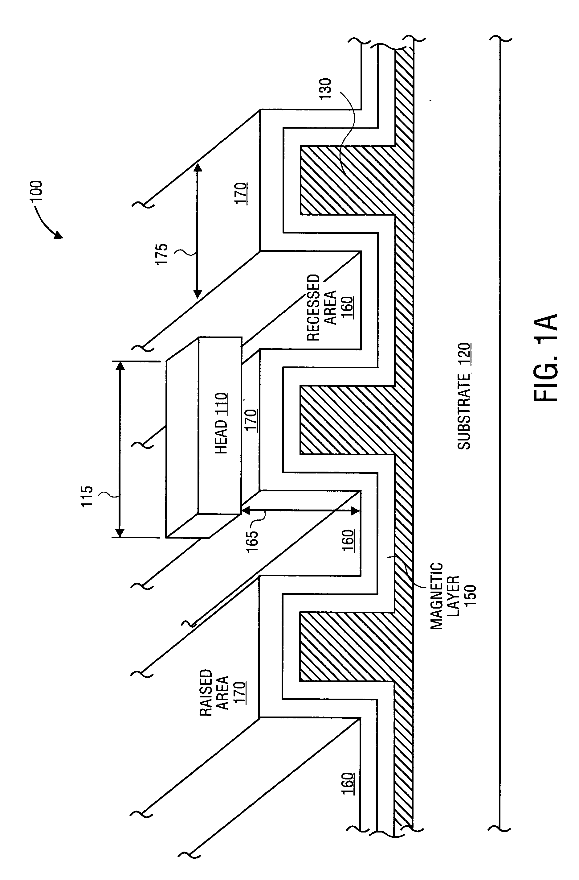
[0019] The terms “above,”“below,” and “between” as used herein refer to a relative position of one layer with respect to other layers. As such, one layer deposited or disposed above or below another layer may be directly in contact with the other layer or may have one or more intervening layers. Moreover, one layer deposited or disposed between layers may be directly in contact with the layers or may have one or more intervening layers.

[0020] It should be noted that the apparatus and methods discussed here...


PUM

PropertyMeasurementUnit
widthaaaaaaaaaa
soft magneticaaaaaaaaaa
magneticaaaaaaaaaa

Abstract

A method of forming a discrete track recording pattern in a magnetic recording disk. In one embodiment, the discrete track recording pattern may be formed in a NiP layer continuous throughout the discrete track recording pattern. Alternatively, the discrete track recording pattern may be formed in a substrate.

Description

TECHNICAL FIELD [0001] Embodiments of this invention relate to the field of disk drives and, more specifically, to disks used in disk drive systems. BACKGROUND [0002] A disk drive system includes one or more magnetic recording disks and control mechanisms for storing data on the disks. The disks are constructed of a substrate, that may be textured, and multiple film layers. In most systems, an aluminum-based substrate is used. However, alternative substrate materials such as glass have various performance benefits such that it may be desirable to use a glass substrate. One of the film layers on a disk is a magnetic layer used to store data. The reading and writing of data is accomplished by flying a read-write head over the disk to alter the properties of the disk's magnetic layer. The read-write head is typically a part of or affixed to a larger body that flies over the disk, referred to as a slider. [0003] The trend in the design of magnetic hard disk drives is to increase the rec...

Claims


Application Information

Patent Timeline
Patent Type & Authority Applications(United States)
IPC IPC(8): G11B5/667G11B5/73G11B5/738G11B5/82G11B5/84G11B5/65G11B5/855G11B5/858
CPCG11B5/667G11B5/8404Y10T29/49021G11B5/858Y10T29/49025G11B5/855
Inventor WACHENSCHWANZ, DAVID E.BERTERO, GERARDO A.TREVES, DAVIDHOMOLA, ANDREWCHAO, JAMES L.BAJOREK, CHRISTOPHER H.
Owner KOMAG
Why Eureka
Try Eureka