
Auto light system

Inactive Publication Date: 2005-02-17
HITACHI LTD +1
View PDF9 Cites 53 Cited by
  • Summary
  • Abstract
  • Description
  • Claims
  • Application Information

AI Technical Summary

Benefits of technology

[0005] It is therefore an object of the present invention to provide an auto light system which is capable of making the driver recognize the light states of plural lights instantly and operate the lights easily.
[0033] In the auto light system so configured as described above, as the light intensity is changed according to the change in the light axis, it will be appreciated that the light intensity can be determined in accordance with the beam direction and the beam range. This means that the adequate light intensity can be determined so as to prevent the driver of the vehicle ahead of the driving vehicle from being dazzled by the head light in existence of the preceding vehicle or the vehicle coming from the opposite direction. In addition, in case that the control system misjudges that there is no preceding vehicle or no vehicle coming from the opposite direction, it will be also appreciated that, by limiting the light intensity of high beam, the driver of the vehicle ahead of the driving vehicle can be prevented from being dazzled by the head light.

Problems solved by technology

In case that those prior art systems are applied to the actual vehicle, when Auto Light state is selected, the driver may have difficulty in identifying the light state as one of four states, Light OFF, Small Light ON and Head Light ON only by observing the condition of the light projected on the road when driving the vehicle at nightfall, in the rain or on the bright street in down town.
In addition, as the light control system controlling the light axis of the head light may change the state of the light continuously more than the prior art system does, the driver may have difficulty in identifying the exact state of the light and the driver may not be able to confirm the light beam distribution, that is, the light direction and range and the light intensity distribution.
In such a case, even if the lighting control is optimized, the driver may fail to confirm the light direction and the light intensity distribution and has no choice but to switch the auto light mode to the manual mode.
In case that the light switch has more refined positions such as Light OFF, Small Light ON, Low Beam (Short Range) ON, Low Beam (Long Range) ON, High Beam (Short Range) ON and High Beam (Long Range) ON, the diver may confuse the light switch operations if the light switch is designed with conventional styles and position transition settings, which may make it rather difficult for the driver to recognize the light states resulted by his or her operations.

Method used


Image

  • Auto light system
  • Auto light system
  • Auto light system

Examples


Embodiment Construction

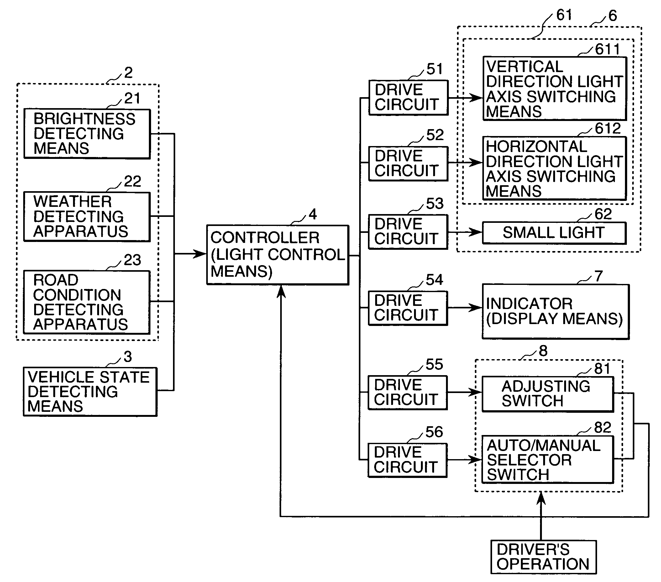
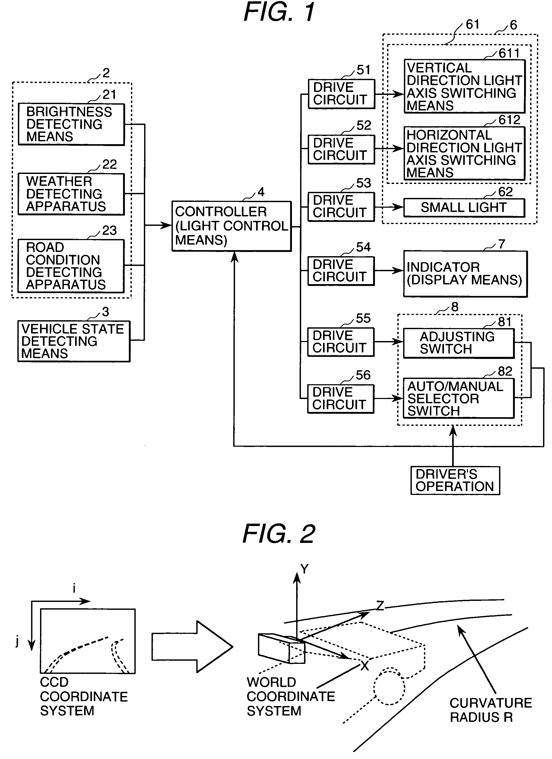
[0048] By referring to attached figures, the embodiment of the auto light system according to the present invention will be described in detail. FIG. 1 shows a control block diagram showing the general configuration of the a uto light system of one embodiment of the present invention.

[0049] As show in FIG. 1, the auto light system of this embodiment comprises the outside environment detecting means 2, the vehicle state detecting means 3, the controller 4, the drive circuits 51 to 56, the light 6, the indicator (display means) 7 and the light switch (manual light operating means) 8.

[0050] The outside environment detecting means 2, comprising the brightness detecting apparatus 21 for detecting the brightness around the vehicle, the weather detecting apparatus 22 for detecting the weather conditions such as fair, rain and fog, the road condition detecting apparatus 23 for detecting the road curvature, and the position of the preceding vehicle and the position of the vehicle coming fr...


PUM


Abstract

To provide an auto light system which allows the driver to confirm the head light beam direction and range easily and to switch the light state easily in the auto light system for controlling the head light beam direction and range. The auto light system comprises a light control means 4 for controlling the light 6 of the vehicle, a manual light operating means 8 for operating manually the light 6, said manual light operating means 8 operated in response to the output signal from the light control means 4, and a display means 7 for displaying the control state of the light 6 controlled by the light control means 4.

Description

BACKGROUND OF THE INVENTION [0001] The present invention relates to an auto light system, specifically to an auto light system of the vehicle having Human Machine Interfaces. [0002] In the prior art of the auto light system for turning ON and OFF the light of the vehicle, the states of the light selectable by the driver are generally four states, Light OFF, Auto Light ON, Small Light ON and Head Light ON, and the driver operates the light switch accordingly in order to specify the state of the light as one of these four states. When the switch is turned to the position of Auto Light ON, the switching ON and OFF of the small light and the head light are operated automatically in response to the surrounding brightness. The driver can recognize the state of the light by observing the light switch positioned at one of four states as described above. The driver may confirm whether or not the light is positioned at high beam by observing the indicator lamp mounted on the panel viewable fr...

Claims


Application Information

Patent Timeline
IPC IPC(8): B60Q1/02B60Q1/06B60Q1/08B60Q1/14B60Q1/18B60Q11/00
CPCB60Q1/06B60Q2300/42B60Q1/143B60Q1/18B60Q2300/056B60Q2300/112B60Q2300/122B60Q2300/128B60Q2300/132B60Q2300/134B60Q2300/136B60Q2300/21B60Q2300/312B60Q2300/322B60Q2300/41B60Q1/085
Inventor FURUSAWA, ISAOMONJI, TATSUHIKOHIGASHINO, JUNIIDA, FUJIO
Owner HITACHI LTD
Learn More