Die pickup method and die pickup device

a pickup device and die technology, applied in the direction of packaging, packaging bottles, loading/unloading, etc., can solve the problems of method, time-consuming, and high risk of die damage, and achieve the effect of reducing the cost of the die pickup system and shortening the pickup tim

Inactive Publication Date: 2005-02-17
SHINKAWA CO LTD
View PDF1 Cites 6 Cited by
  • Summary
  • Abstract
  • Description
  • Claims
  • Application Information

AI Technical Summary

Benefits of technology

[0007] The object of the present invention is to provide a die pickup method and a die pickup device (jig) that shorten the pickup time and lower the cost of die pickup system.

Problems solved by technology

However, this method has a problem.
In cases where the thickness of the die is small, i.e., approximately 100 μm or less, the die is likely to be damaged.
Accordingly, it takes time, and the productivity is poor.
Furthermore, a driving means is needed in order to drive the suction stage or to drive the protruding portion of the suction stage, causing the die pickup system to be expensive.

Method used


Image

  • Die pickup method and die pickup device
  • Die pickup method and die pickup device
  • Die pickup method and die pickup device

Examples


Embodiment Construction

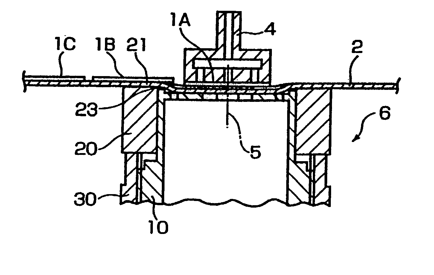
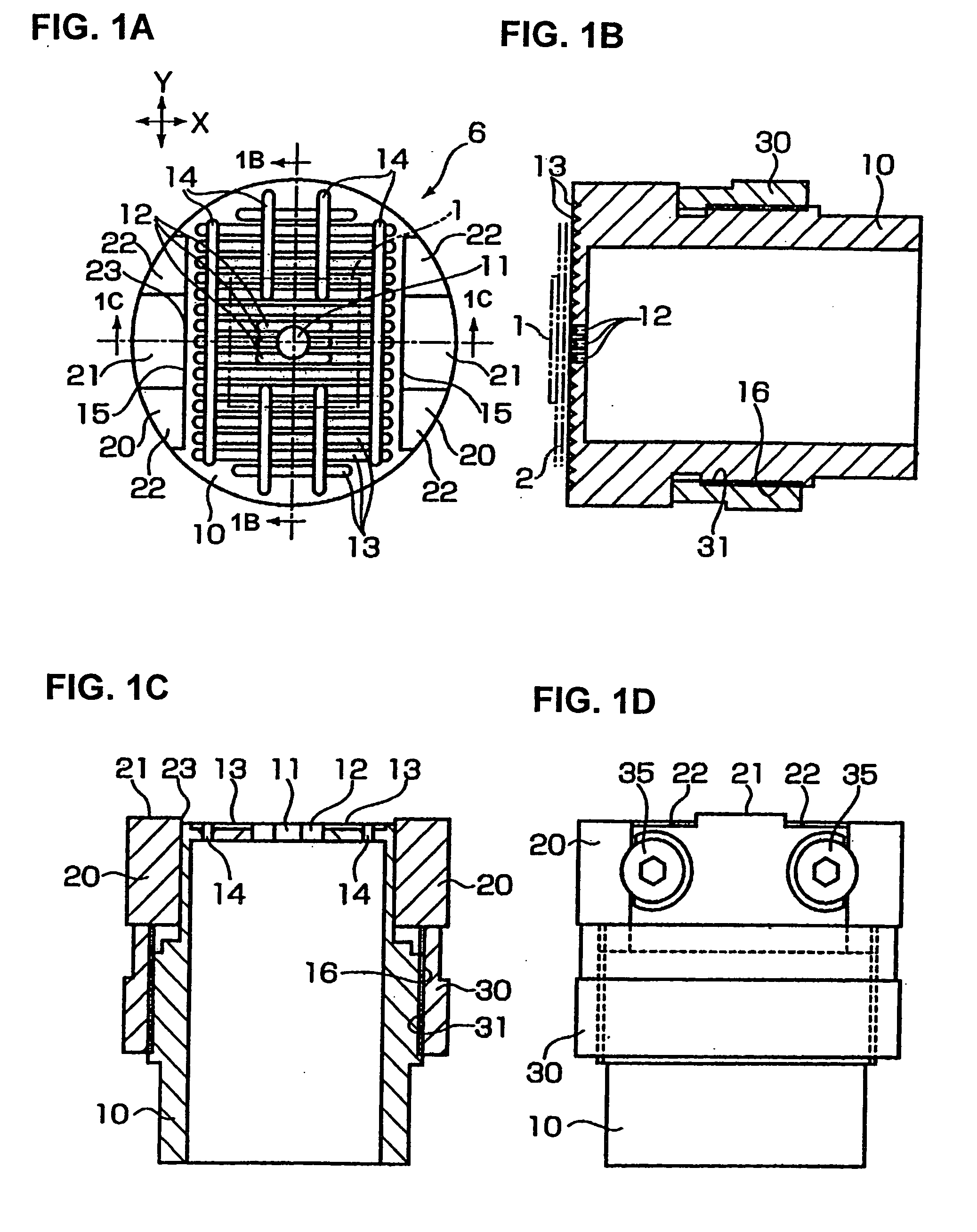
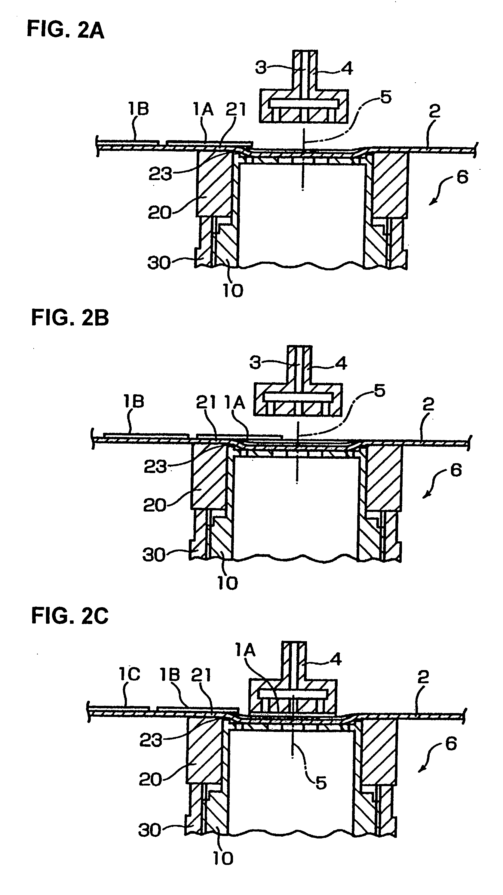
[0024] The outer circumference of a wafer sheet 2 on which dies 1A, 1B, 1C . . . are bonded as shown in FIGS. 2A through 2C is fastened to a wafer ring (not shown in the drawings); and this wafer ring is fastened to a wafer supporting frame (not shown in the drawings) that is driven in the directions of the X and Y axes in the horizontal plane (see FIG. 1A). Each die 1A, 1B, 1C . . . is vacuum-chucked and picked up by a collet 4 in which suction chucking holes 3 are formed. A suction stage 6 that vacuum-sucks the wafer sheet 2 is provided beneath the collet 4 so that the die pickup center 5 of the suction stage 6 is aligned with the center of suction chucking hole 3 of the collet 4.

[0025] The structure described so far above belongs to a known technique.

[0026] As shown in FIGS. 1A through 1D, the suction stage 6 is comprised of a suction tube 10, side blocks 20 that are provided on the upper portions of both side surfaces (see FIG. 1A) of this suction tube 10, and an adjustment nu...


PUM


Abstract

A die pickup method and device including a collet 4 that vacuum-chucks dies 1A, 1B, IC . . . , which are on a wafer sheet 2, and a suction stage 6, which vacuum-sucks this wafer sheet 2. A protruding surface 21 is formed on the upper surface of the suction stage 6 so that it is located on the feeding (upstream) side in the direction in which dies are fed to the die pickup center 5 of the suction stage 6. The wafer sheet 2 being vacuum-sucked by the suction stage 6 is fed so that a die 1A that is to be picked up is moved toward the die pickup center 5, thus allowing the die 1A to be separated from the wafer sheet 2 as the die 1A passes the protruding surface 21, and then the die 1A is vacuum-chucked and picked up by the collet 4.

Description

BACKGROUND OF THE INVENTION [0001] 1. Technical Field [0002] The present invention relates to a die pickup method and a die pickup device (jig) which peel dies, which are bonded to a wafer sheet, away from this wafer sheet and pick up these dies. [0003] 2. Description of the Related Art [0004] Generally, a push-up needle system is used as a die pickup method for dies that are bonded to a wafer sheet. However, this method has a problem. In cases where the thickness of the die is small, i.e., approximately 100 μm or less, the die is likely to be damaged. [0005] Japanese Patent Application Laid-Open (Kokai) No. 2001-118862 (Japanese Patent No. 3209736), ameliorating the above-described problem, discloses a method that picks up dies from a wafer sheet without using a push-up needle. Seven embodiments are involved in this prior art; and in all of these embodiments, a die that is to be picked up is moved to a die pickup center, after which the die is held by a collet and is then peeled aw...

Claims


Application Information

Patent Timeline
Patent Type & Authority Applications(United States)
IPC IPC(8): H01L21/67H01L21/00H01L21/52H01L21/68
CPCH01L21/67132H01L21/68
Inventor TAKEUCHI, TAKASHIKOBAYASHI, TAITO
Owner SHINKAWA CO LTD
Why Eureka
Try Eureka