Motor cooling structure of vacuum manipulator and cooling method thereof

A vacuum manipulator and motor cooling technology, applied in electromechanical devices, cooling/ventilation devices, circuits, etc., can solve the problems of increasing the difficulty and cost of cavity structure processing, longer response time, longer transit time, etc., to facilitate miniaturization The design, installation and debugging are simple, and the effect of reducing processing difficulty and cost

Pending Publication Date: 2022-07-22
SUZHOU ZISHAN SEMICON TECH CO LTD
View PDF0 Cites 0 Cited by
  • Summary
  • Abstract
  • Description
  • Claims
  • Application Information

AI Technical Summary

Problems solved by technology

The complex structure makes its response time longer, and the larger mechanical size requires the design of a larger vacuum chamber to accommodate the vacuum robot arm, which forces the size of the entire machine to become larger, thereby increasing the difficulty and cost of cavity structure processing; On the other hand, the manipulator will need to complete a longer travel distance due to the larger chamber environment to complete a wafer handling operation, further prolonging the transfer time

Method used


Image

  • Motor cooling structure of vacuum manipulator and cooling method thereof
  • Motor cooling structure of vacuum manipulator and cooling method thereof

Examples


Embodiment Construction

[0024] The present invention will be further described in detail below with reference to the accompanying drawings and specific embodiments.

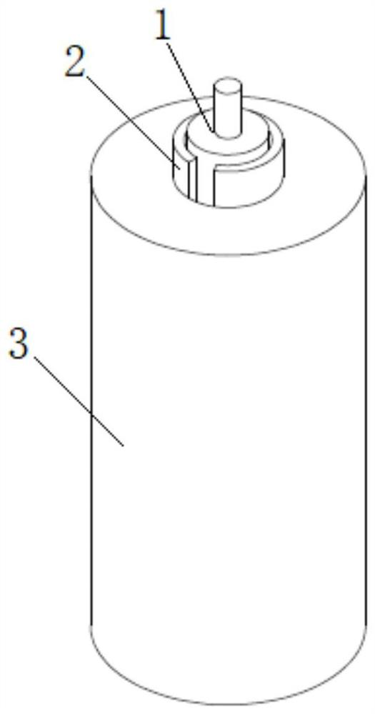
[0025] attached Figure 1-2 The motor cooling structure of the vacuum manipulator according to the present invention includes a motor 1, a semiconductor refrigeration sheet 2, and a metal structural member 3;

[0026] The motor 1 is arranged in the vacuum chamber 4;

[0027] The semiconductor refrigeration sheet 2 is also arranged in the vacuum chamber 4, and the cold end is attached to the motor 1, and the hot end is attached to the metal structural member 3;

[0028] The metal structure 3 is arranged on the vacuum chamber 4 , and a part is located in the vacuum chamber 4 , and the remaining part extends out of the vacuum chamber 4 .

[0029] Further, the end of the metal structure 3 extending out of the vacuum chamber 4 is provided with a heat sink 5, which can further improve the heat dissipation efficiency.

[0030] Further, the ...


PUM


Abstract

The invention relates to a motor cooling structure of a vacuum manipulator and a cooling method thereof. The motor cooling structure comprises a motor, a semiconductor chilling plate and a metal structural member, the motor is arranged in the vacuum cavity; the cold end of the semiconductor chilling plate is attached to the motor, and the hot end is attached to the metal structural part. The metal structural part is arranged on the vacuum cavity, part of the metal structural part is located in the vacuum cavity, and the rest of the metal structural part extends out of the vacuum cavity. The motor can be cooled through the semiconductor chilling plate, heat generated by the semiconductor chilling plate is transmitted to the atmospheric environment through the metal structural part, and therefore the cooling purpose is achieved, the power transmission structure of the vacuum mechanical arm is greatly simplified, the vacuum cavity is shrunk, and the mechanical arm is more compact. And the mechanical track of the arm can be optimized by adding a small motor at a key position, so that the stroke is further shortened, and the speed of completing one-time wafer transfer by the vacuum manipulator is improved.

Description

technical field [0001] The invention relates to the technical field of vacuum heat dissipation, in particular to a motor cooling structure of a vacuum manipulator and a cooling method thereof. Background technique [0002] The vacuum robot used in semiconductor processing engineering is the key automation equipment responsible for the transfer of wafers between different stations in a vacuum environment. The transfer speed of the transmission system where the vacuum manipulator is located largely dominates the production speed of the entire semiconductor machine, which greatly affects its production efficiency. [0003] In a vacuum environment, the only way of heat transfer is thermal radiation. The efficiency of heat transfer by thermal radiation is not enough to transfer the heat generated by the motor in a vacuum environment to the outside, causing the temperature of the motor body to rise. Above the temperature threshold for normal operation of the motor, the motor wil...

Claims


Application Information

Patent Timeline
Patent Type & Authority Applications(China)
IPC IPC(8): H01L21/687H02K9/00
CPCH01L21/68707H02K9/00
Inventor 周玉龙
Owner SUZHOU ZISHAN SEMICON TECH CO LTD
Why Eureka
Try Eureka