Blind mating apparatus

a technology of blind mating and assembly steps, which is applied in the direction of coupling contact members, coupling device connections, printed circuits, etc., can solve the problems of not being able to reduce manufacturing costs, many manufacturing steps, and complex manufacturing steps for manufacturing assembly of blind mating connectors, so as to reduce manufacturing costs and simplify assembly steps

Inactive Publication Date: 2005-02-17
GUAN TECH
View PDF7 Cites 11 Cited by
  • Summary
  • Abstract
  • Description
  • Claims
  • Application Information

AI Technical Summary

Benefits of technology

[0006] A primary object of the present is to provide a blind mating apparatus utilizing a printed circuit board (PCB) mating with a spring to form a board-to-board connection to mate correctly within a bias for the reason that a conducting pad is adjustable. Thus correct connection is achieved, while assembly steps are simplified, the connection is made adjustable, and manufacturing costs are reduced as well.

Problems solved by technology

Manufacturing assembly of the blind mating connector requires many complex steps, much manufacturing time, and cannot reduce manufacturing costs.
Also, the blind mating connector has a fixed numbers of terminals and conducting pads, a numbers of fixed distances each between the conducting pads, and a fixed volume thereof, such that the blind mating connector cannot be further adjusted.

Method used


Image

  • Blind mating apparatus
  • Blind mating apparatus
  • Blind mating apparatus

Examples


Embodiment Construction

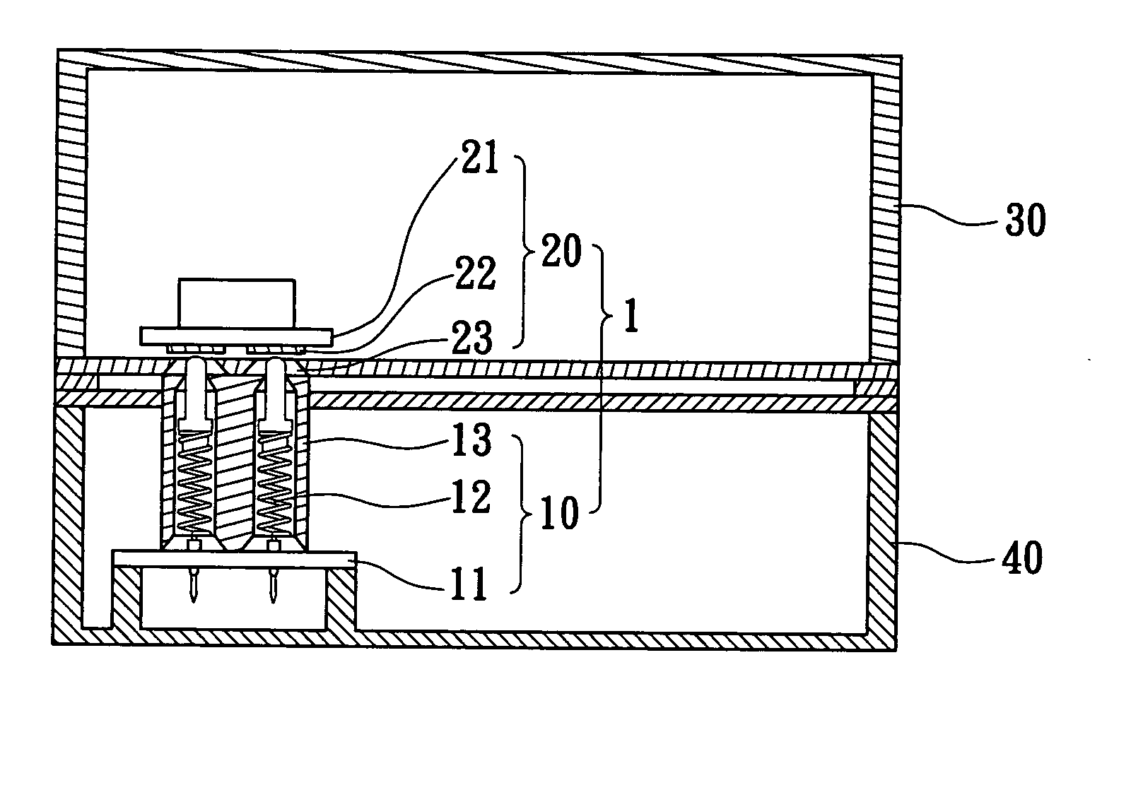
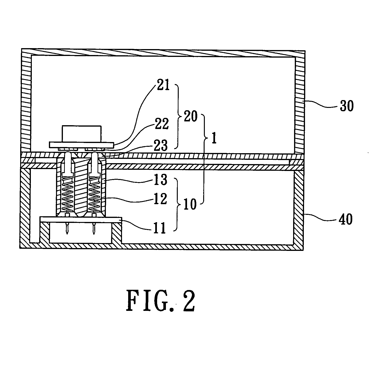
[0018] Referring to FIG. 2 and FIG. 3, a blind mating apparatus 1 according to the present invention is applied as an expansion system. The expansion system has a first module 30 and a second module 40 expandably mating with the first module 30, the first module 30 and the second module 40 respectively have connecting signals relative to each other. The blind mating apparatus 1 includes a contacting unit 10 and a guiding unit 20 relatively mating with the first module 30 for expandably connecting the second module 40 to the first module 30. The contacting unit 10 includes a first printed circuit board (PCB) 11, a resilient member 12 and a housing 13. The first PCB 11 is located in the second module 40, the resilient member 12 electrically connects to the first PCB 11, and the housing 13 sleeves on the resilient member 12. The guiding unit 20 includes a second PCB 21, a contacting member 22 and a guiding member 23. The second PCB 21 is located in the first module 30. The contacting m...


PUM


Abstract

A blind mating apparatus used in an expansion system has a first printed circuit board (PCB) and a second PCB. The first PCB has a resilient member and a housing sleeving the resilient member, and the second PCB has a contact member electrically connecting the resilient member. The blind mating apparatus further has a guiding member for guiding the resilient member and through which the resilient member penetrates. The contact member has a tolerance for correctly mating with the resilient member while the resilient member provides the contact member with a little bias.

Description

BACKGROUND OF THE INVENTION [0001] 1. Field of the Invention [0002] The present invention relates to a blind mating apparatus. More particularly, the present invention relates to a blind mating apparatus adopted for an expanding paper drawer. [0003] 2. Description of Related Art [0004] Referring to FIG. 1, a prior art office peripheral system 30a, which includes a printer, a copier, a fax machine and so on, utilizes one expanding paper drawer 40a, satisfying a user for paper size and paper requirement. A way of connection between one expanding paper drawer 40a and another expanding paper drawer 40a or one expanding paper drawer 40a and the prior art office peripheral system 30a is to employ a couple of blind mating connectors, each having a tolerance for correctly mating for each other when one blind mating connector provides a little bias to the other blind mating connector. [0005] U.S. Pat. No. 4,988,308 discloses a blind mating connector characterized by a minor cross sectional d...

Claims


Application Information

Patent Timeline
Patent Type & Authority Applications(United States)
IPC IPC(8): H01R13/24H01R13/631
CPCH01R13/6315H01R13/2421
Inventor LAN, CHI FENG
Owner GUAN TECH
Why Eureka
Try Eureka