
Driveshaft assembly with retention mechanism

a technology of drive shaft and retention member, which is applied in the direction of bearing unit rigid support, furniture parts, couplings, etc., can solve the problems of high manufacturing cost, limited serviceability, and excessive machining requirements, and achieve the effect of reducing the number of components and cos

Inactive Publication Date: 2005-02-17
AMERICAN AXLE & MFG
View PDF11 Cites 12 Cited by
  • Summary
  • Abstract
  • Description
  • Claims
  • Application Information

AI Technical Summary

Benefits of technology

[0006] Accordingly, the present invention is directed to overcoming the disadvantages commonly associated with the manufacture and subsequent service of conventional universal joints. Therefore, it is an object of the present invention to reduce the number of components and cost required to construct an easily serviceable universal joint assembly.

Problems solved by technology

However, this method has one or more disadvantages such as, for example, excessive machining requirements, limited serviceability, and high cost of manufacture.
However, due to the dimensional variation of each component, either an interference condition or an excess clearance between the bearing cup and the snap ring is accumulated.
Other universal joint retention devices attempt to compensate for the dimensional variation in the components but sacrifice serviceability.

Method used


Image

  • Driveshaft assembly with retention mechanism
  • Driveshaft assembly with retention mechanism
  • Driveshaft assembly with retention mechanism

Examples


Embodiment Construction

[0015] In general, the present invention is directed to a universal joint of the type used in motor vehicle driveline applications for interconnecting rotating shafts in a manner permitting changes in angularity therebetween.

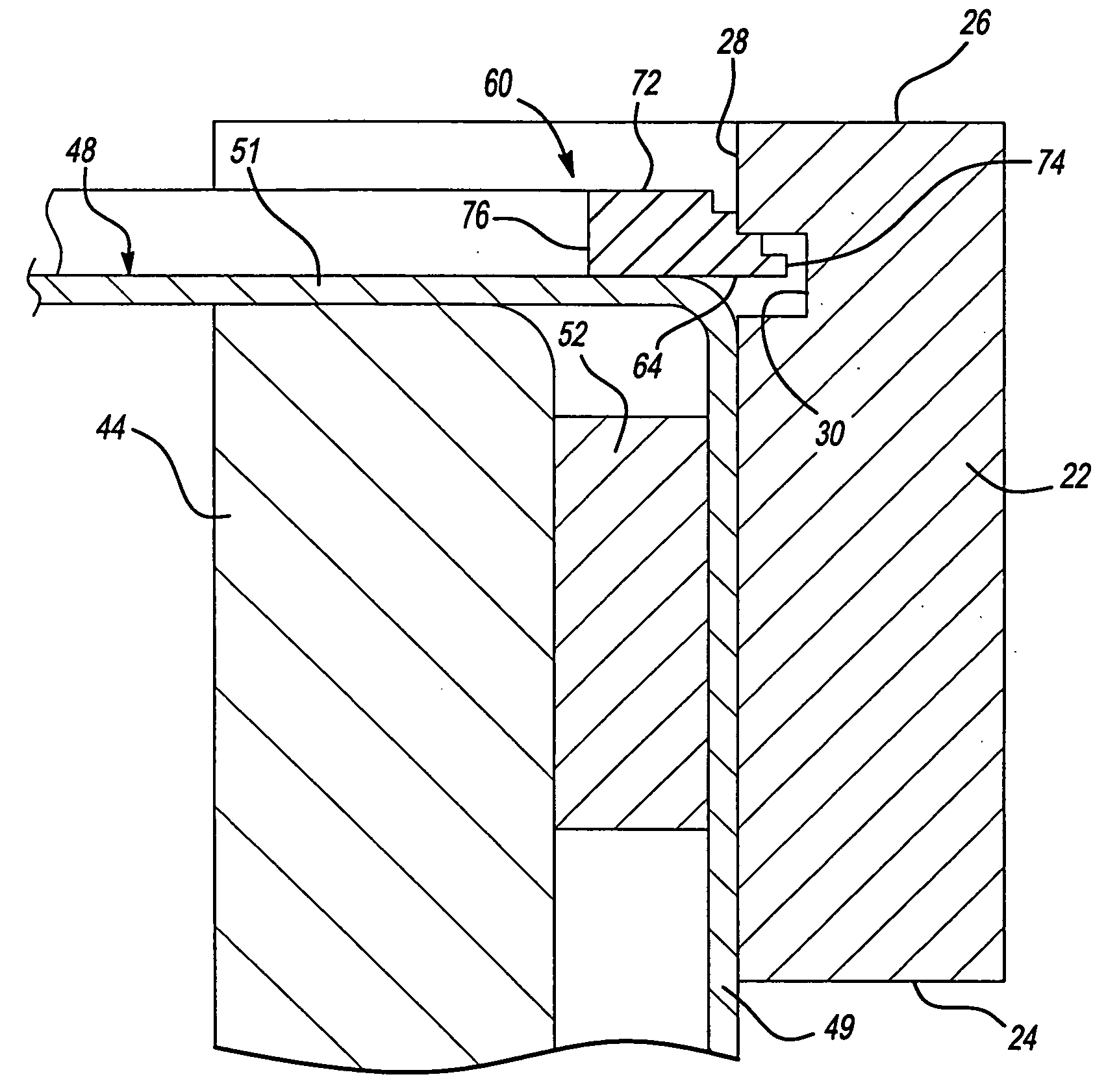
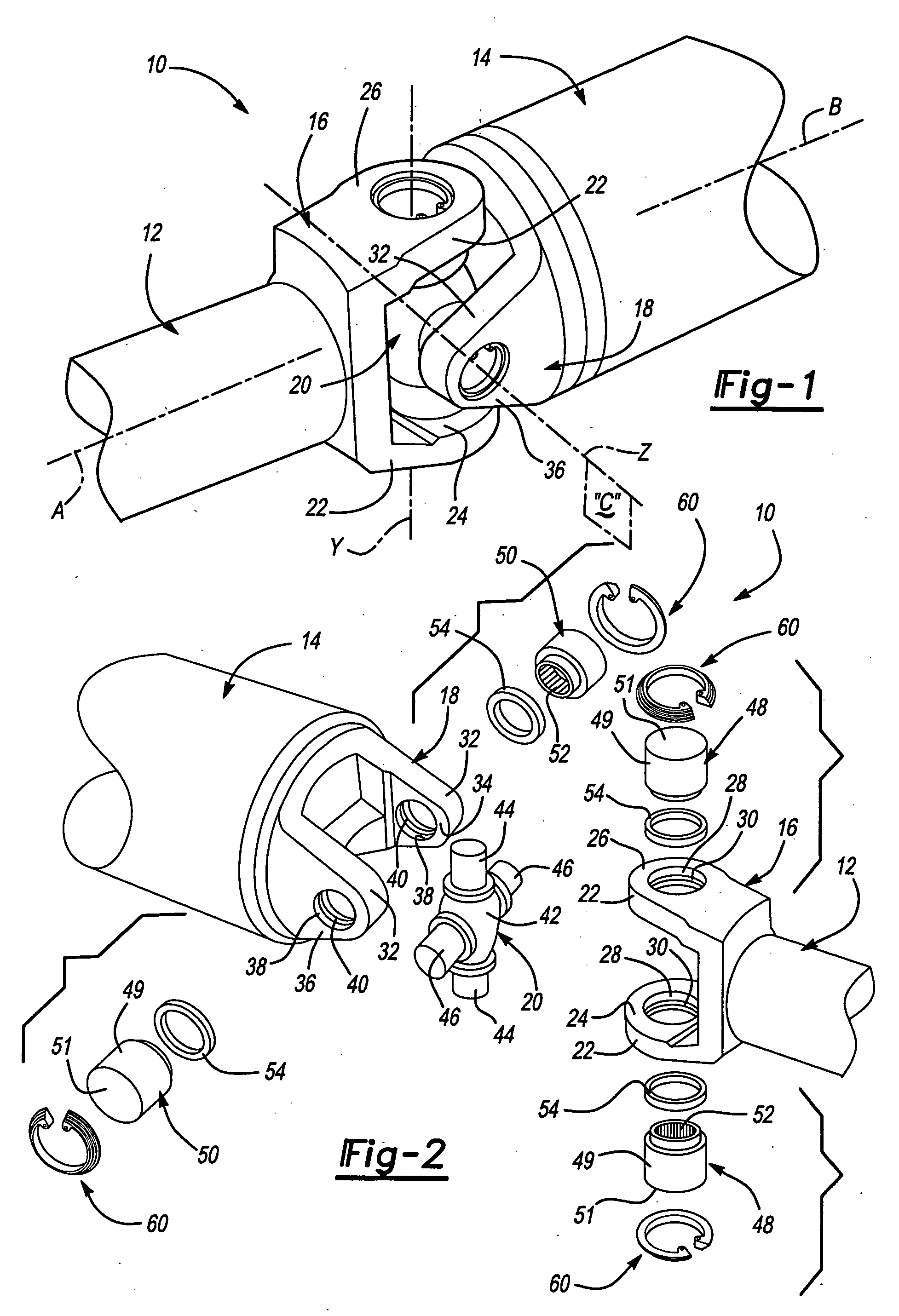
[0016] Referring to FIGS. 1 and 2, a universal joint 10 is shown connecting a first shaft 12 to a second shaft 14. In general, universal joint 10 includes a first yoke 16 attached to an end of first shaft 12, a second yoke 18 attached to an end of second shaft 14 and a cruciform 20 interconnecting first yoke 16 to second yoke 18. The first yoke 16 is bifurcated and includes a pair of laterally spaced-apart legs 22 which are preferably symmetrical with respect to the rotary axis of first shaft 12, as denoted by construction line A. Legs 22 include an inboard surface 24 and an outboard surface 26 with an aperture 28 extending therebetween. Apertures 28 are aligned on a first trunnion axis, as denoted by construction line Y, which passes through and is orthogonal ...


PUM


Abstract

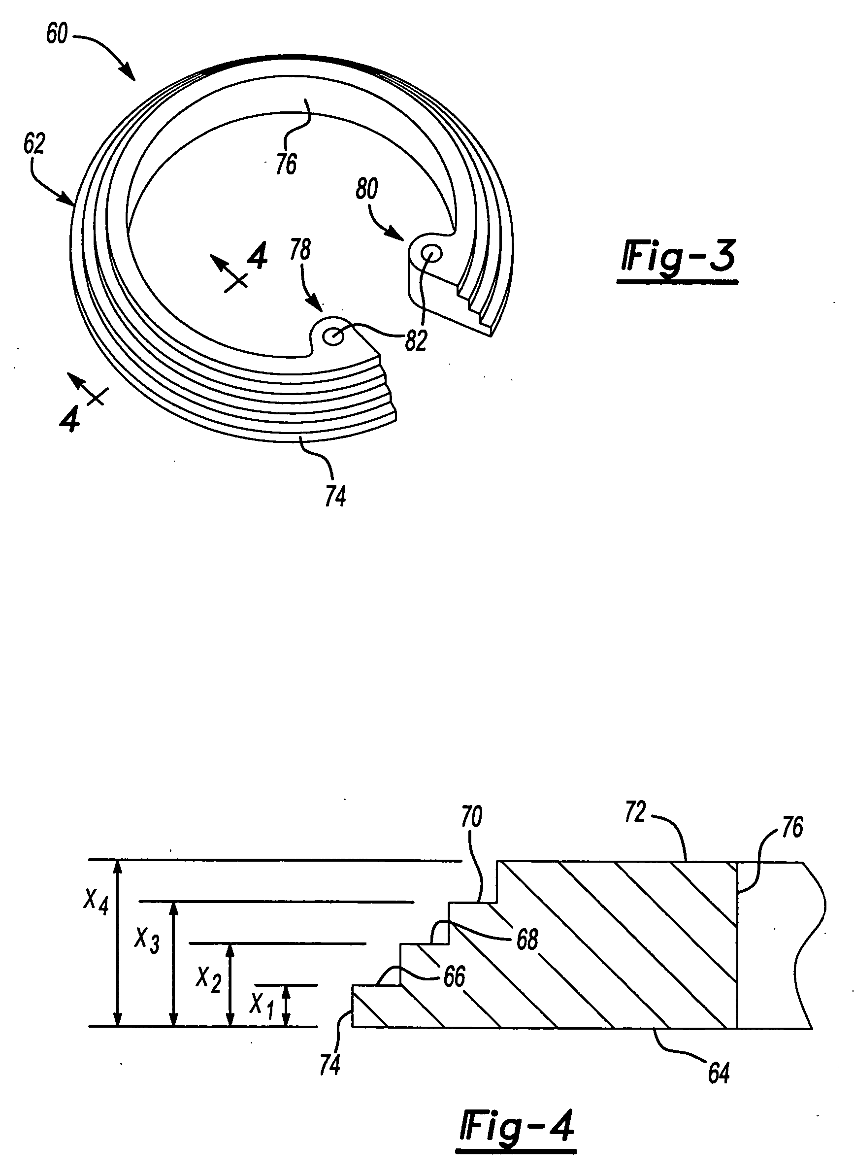
A universal joint includes a yoke with a leg having an aperture extending therethrough. The aperture includes an annular groove. The universal joint also includes a cruciform having a trunnion, a bearing cup positioned in the aperture and mounted on the trunnion and a retention member including a stepped cross-section. The retention member is disposed within the groove to fill the gap remaining between the groove edge and the bearing cup.

Description

CROSS-REFERENCE TO RELATED APPLICATIONS [0001] This application is a continuation of U.S. patent application Ser. No. 10 / 372,998 filed on Feb. 24, 2003. The entire disclosure of the above application is incorporated by reference herein.BACKGROUND OF THE INVENTION [0002] The present invention generally relates to a universal joint for use in a driveline of a motor vehicle. More specifically, the present invention pertains to a universal joint equipped with a retention member for securing a bearing cup in a yoke. [0003] As is commonly known, universal joints are used in motor vehicle driveline applications for interconnecting a pair of rotary shafts and permitting changes in angularity therebetween. Many conventional universal joints include a pair of bifurcated yokes which are secured to the rotary shafts. The bifurcated yokes are interconnected by a spider or a cruciform for rotation about independent axes. The spider includes four orthogonal trunnions with each opposing pair of axi...

Claims


Application Information

Patent Timeline
Patent Type & Authority Applications(United States)
IPC IPC(8): F16D3/38
CPCY10S403/07F16D3/382F16C35/067F16C21/005F16C2361/41F16B21/183F16D3/38
Inventor BOMMARITO, MICHAEL J.GILLIHAN, STEVEN P.FLANAGAN, JOSEPH P.
Owner AMERICAN AXLE & MFG
Learn More