Heart holder

Inactive Publication Date: 2005-02-17
KARL STORZ GMBH & CO KG
View PDF7 Cites 6 Cited by
  • Summary
  • Abstract
  • Description
  • Claims
  • Application Information

AI Technical Summary

Benefits of technology

[0037] This measure has the advantage that the arm can be locked and fixed after it has been suitably oriented. This also opens up the possibility of changing the orientation of the arm during the operation, that is to say while the heart is held up by the device

Problems solved by technology

Since the heart is still beating, the problem which arises is that of holding a pulsating organ in a lifted position for the duration of an operation.
Because so many holding elements, namely six, are present, it is necessary to have a large number of bearing points and holding points on the outer surface of the

Method used


Image

  • Heart holder
  • Heart holder
  • Heart holder

Examples


Embodiment Construction

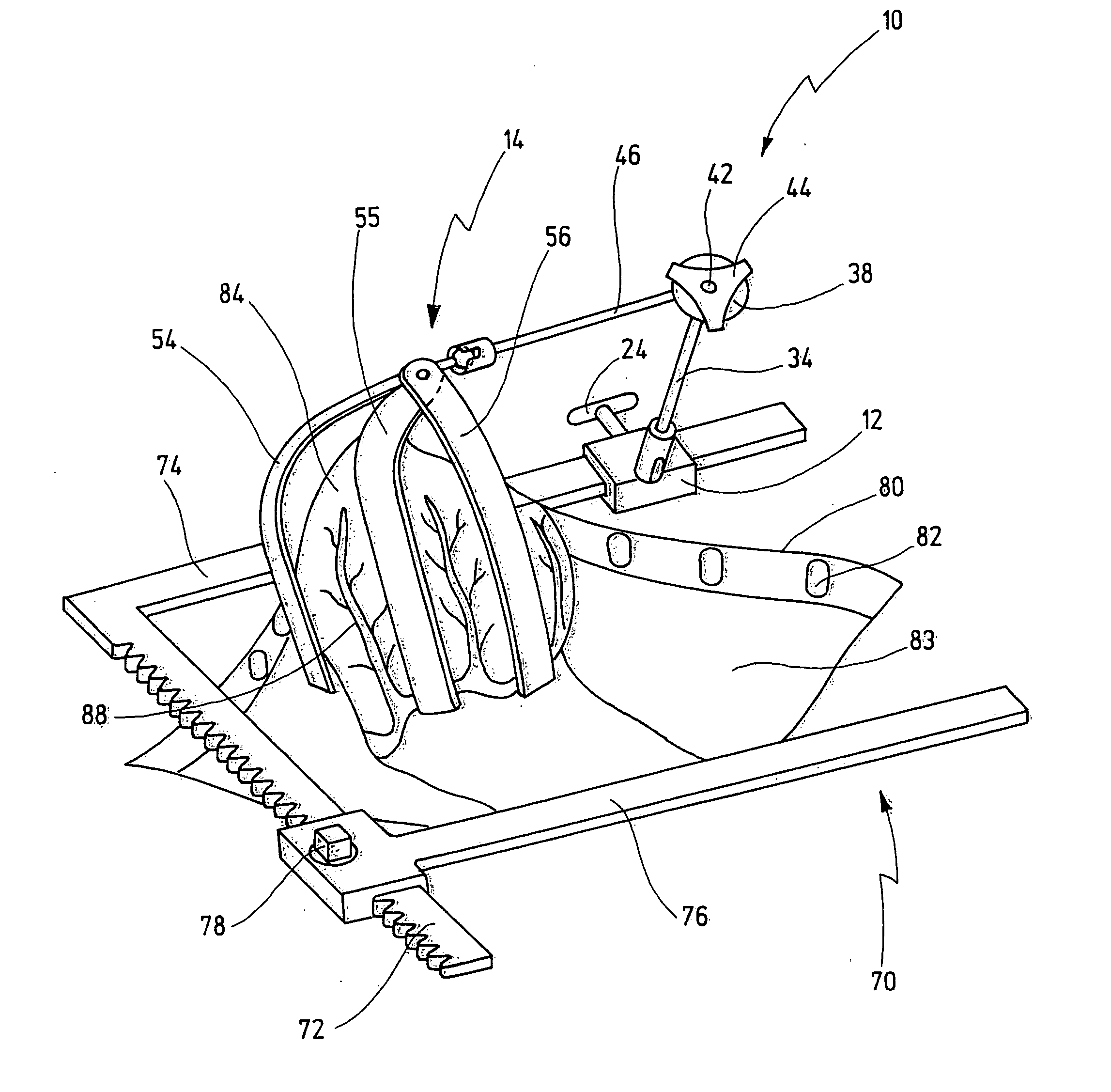
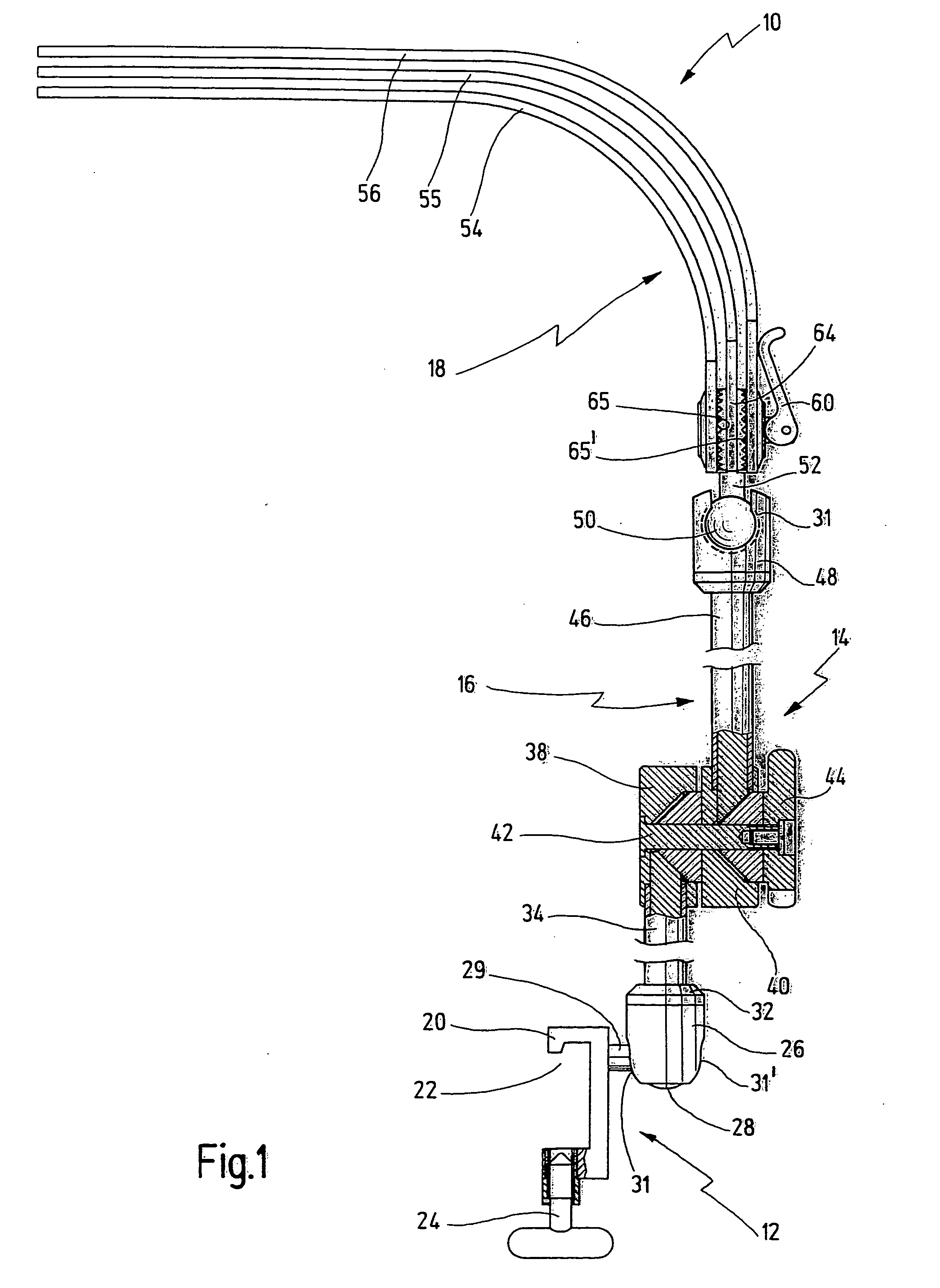
[0047] A functional element shown in FIG. 1 is designated overall by reference number 10.

[0048] The functional element 10 has a securing device 12 with which, as will be explained in greater detail below in connection with FIG. 4, it can be mounted on a retractor 70.

[0049] The functional element 10 also has a device 14 for holding a heart 84.

[0050] This device 14 has an arm 16 which projects from the securing device 12 and at whose outer end the actual heart holder 18 is arranged.

[0051] The securing device 12 has a block 20 in which a recess 22 is provided which corresponds to the contour of a rail 74 of the retractor 70, as can be seen from FIG. 4. The block 20 can be pushed onto the rail 74 from the outer end. A locking screw 24 is provided in order to secure the securing device 12 in position on the retractor 70.

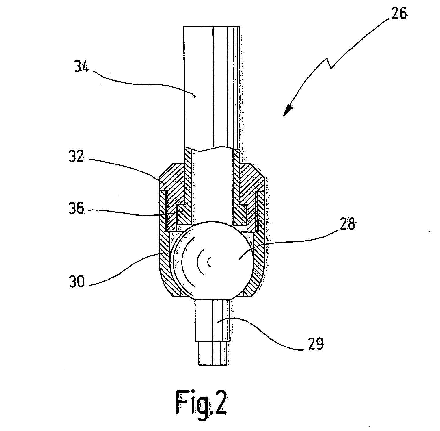
[0052] The block 20 is connected to a first ball-and-socket joint 26.

[0053] Such a ball-and-socket joint 26 is shown on an enlarged scale in cross section in FIG. 2...


PUM


Abstract

A functional element to be mounted on a retractor for performing cardiothoracic surgery has a securing device for mounting it releasably on the retractor. A device for holding up a beating heart lifted from an operating site has several spreadable strip-shaped holding fingers. It is proposed that three or four strip-shaped holding fingers are present which are designed to be bendable so that they can be shaped to form a holding basket adapted to the particular heart which is to be held.

Description

CROSSREFERENCE OF PENDING APPLICATION [0001] This application is a continuation of pending international application PCT / EP03 / 01206 filed on Feb. 7, 2003 which designates US and which claims priority of European patent application No. 02 002 860.1 filed on Feb. 8, 2002.BACKGROUND OF THE INVENTION [0002] The present invention relates to a functional element to be mounted on a retractor for performing cardiothoracic surgery, with a securing device for mounting it releasably on the retractor, and with a device which is used for holding up a beating heart lifted from an operating site and has several spreadable strip-shaped holding fingers. [0003] A functional element of this kind is known from U.S. Pat. No. 6,019,722. [0004] A retractor has a toothed rail, from which a first holding rail is angled off, and a second holding rail which can be driven along the toothed rail via a drive mechanism and which extends parallel to the first holding rail and can be moved toward and away from the ...

Claims


Application Information

Patent Timeline
IPC IPC(8): A61B17/00A61B17/02A61B17/30A61B19/00
CPCA61B17/0206A61B2017/301A61B2017/00243A61B19/26A61B90/50
Inventor SCHOLLHORN, JOACHIM
Owner KARL STORZ GMBH & CO KG
Why Eureka
Try Eureka