Manipulatable delivery catheter for occlusive devices (II)

Inactive Publication Date: 2005-02-17
MICRUS ENDOVASCULAR CORP
View PDF62 Cites 105 Cited by
  • Summary
  • Abstract
  • Description
  • Claims
  • Application Information

AI Technical Summary

Benefits of technology

[0012] In taking advantage of the flexibility and capabilities of the present invention, a variation capable of twisting in a helical or corkscrew-like manner may be accomplished with or without an inflatable member or balloon region. This variation is particularly useful in traversing tortuous vasculature and in making difficult approaches to aneurysms. This alternative varation utili

Problems solved by technology

Often the target site of the malady is difficult to reach.
Inadvertent embolism due to an inability to contain the fluid agent within the aneurysm is one risk which may occur when using fluid emb

Method used


Image

  • Manipulatable delivery catheter for occlusive devices (II)
  • Manipulatable delivery catheter for occlusive devices (II)
  • Manipulatable delivery catheter for occlusive devices (II)

Examples


Example

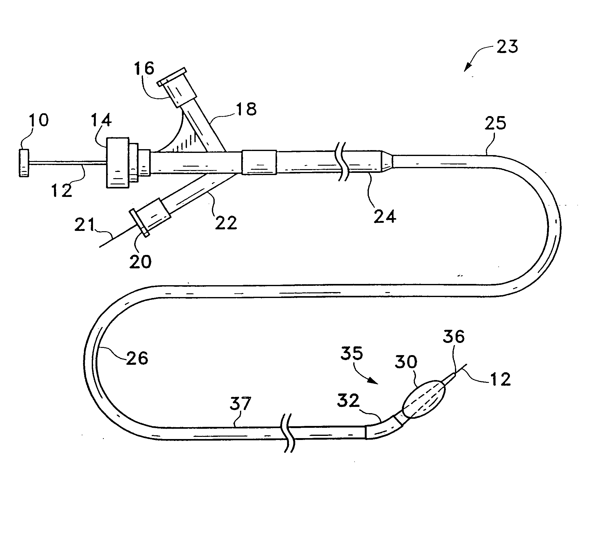
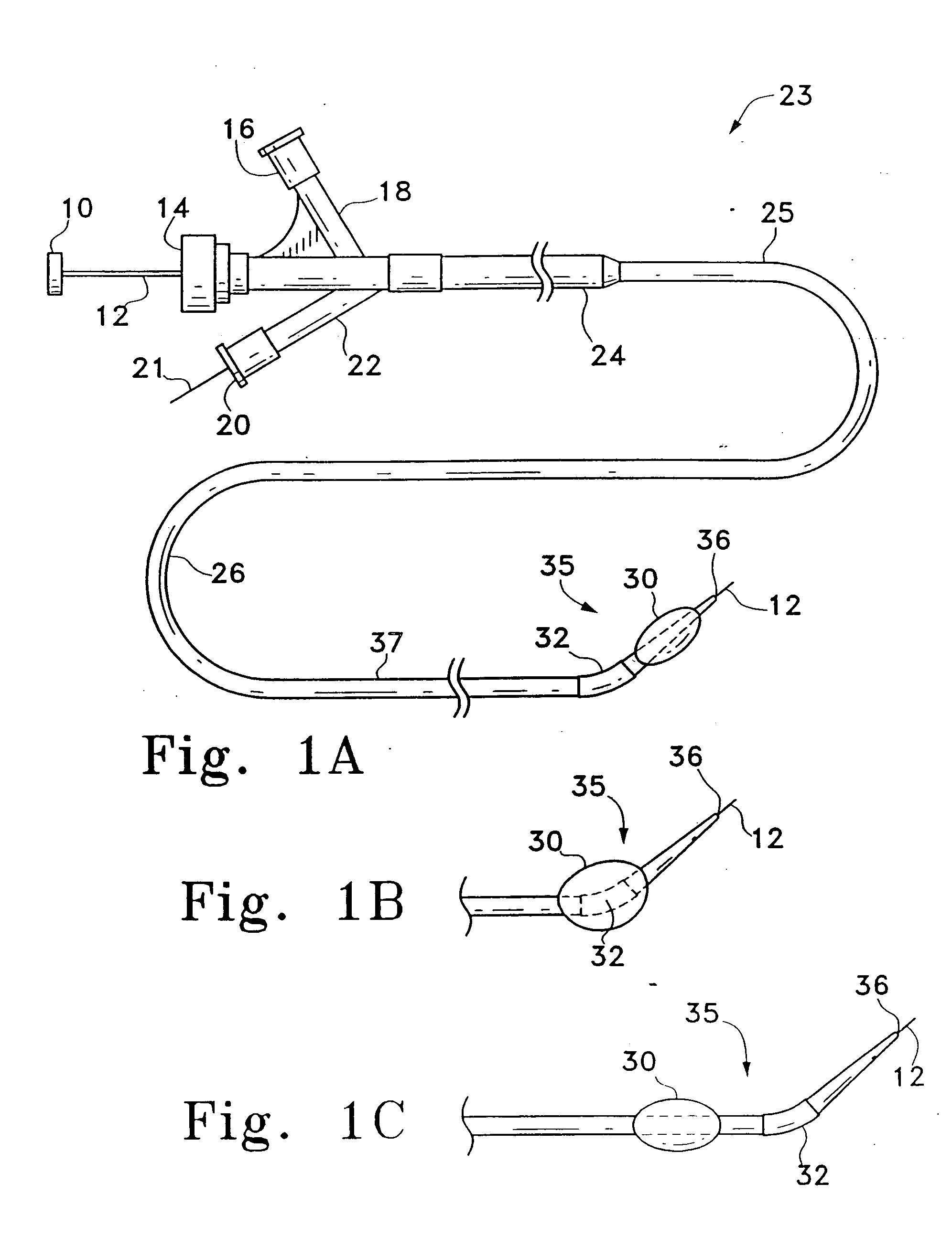
[0039] This invention involves a multi-lumen, catheter having a manipulatable distal tip and is for the delivery of vaso-occlusive materials or implants. The inventive catheter may include one or more distally placed balloon members. The device is shown in detail in the Figures wherein like numerals indicate like elements. The catheter preferably includes a shapeable, flexible distal section. The flexible section, or “hinge region”, preferably is manipulated from outside the body during the process of delivering the verso-occlusive device or material. The terms “hinge region”, “hinge”, or “flexible joint” may be used interchangeably for our applications.

[0040]FIG. 1A shows a catheter assembly 23 made according to one variation of the invention. This variation of the catheter assembly 23 includes a catheter shaft 25 comprised of a flexible, thin walled body or tube 26 having an inner lumen which extends between proximal and distal catheter ends 24, 37, respectively. The tube 26 is p...


PUM


Abstract

This is in the general field of surgical instruments and is specifically a delivery catheter with a flexible, proximally-manipulated hinge or joint region. The inventive catheter may have a balloon region. The catheter may have a shaft of varying flexibility which contains several lumen. The inner, or delivery, lumen generally may be used with a guidewire to access target sites within the body via the flexible, small diameter vessels of the body. The delivery lumen may be also used for placement of occlusive materials, e.g., in an aneurysm. Inflation of the micro-balloon, located near the distal tip of the catheter, is effected using the inflation lumen. The push/pull wire lumen contains a wire, which when manipulated, flexes the catheter's distal tip. The push/pull wire tubing may have a variable thickness to aid in adjusting the degree of flexibility. Moreover, the delivery catheter may be capable of twisting in a helical or corkscrew-like manner for traversing certain vasculature. This may be accomplished by winding the push/pull wire within the catheter and fixedly attaching it. The catheter may further include an entry in the catheter wall to allow for the insertion of a guidewire; this may facilitate the rapid exchange of catheter devices as desired by the user.

Description

RELATED APPLICATIONS [0001] This application is a continuation of U.S. patent application Ser. No. 10 / 184,561, filed on Jun. 27, 2002, which is a divisional of U.S. patent application Ser. No. 09 / 703,468 entitled, MANIPULATABLE DELIVERY CATHETER FOR OCCLUSIVE DEVICES (II), filed on Oct. 31, 2000, which is a continuation-in-part of U.S. patent application Ser. No. 09 / 643,085 entitled MANIPULATABLE DELIVERY CATHETER FOR OCCLUSIVE DEVICES, filed Aug. 21, 2000, now pending and incorporated by reference in its entirety.FIELD OF THE INVENTION [0002] This invention is in the general field of surgical instruments and is specifically a catheter having a flexible, proximally-manipulated hinge region. The inventive catheter may include a balloon. The catheter may have a shaft of varying flexibility which contains several lumen. The inner, or delivery, lumen generally may be used with a guide wire to access target sites within the body through the flexible, small diameter vessels of the body. T...

Claims


Application Information

Patent Timeline
IPC IPC(8): A61M25/01A61M25/10
CPCA61B17/12022A61M2025/1052A61B17/12113A61B17/12136A61B17/1214A61B2017/1205A61M25/0053A61M25/0054A61M25/0147A61M25/10A61M25/1006A61M2025/0034A61M2025/0037A61M2025/0039A61M2025/004A61M2025/0177A61M2025/018A61B17/1204A61M25/0144
Inventor HEBERT, STEPHENLEVINE, MARC-ALAN
Owner MICRUS ENDOVASCULAR CORP
Why Eureka
Try Eureka