Modular fuel injector with a deep pocket seat and method of maintaining spatial orientation

a fuel injector and deep pocket technology, applied in the direction of fuel injection apparatus, fuel feed system, spraying apparatus, etc., can solve the problems of fuel spray pattern and targeting unsuitability, affecting emission,

Active Publication Date: 2005-02-24
VITESCO TECH USA LLC
View PDF6 Cites 24 Cited by
  • Summary
  • Abstract
  • Description
  • Claims
  • Application Information

AI Technical Summary

Benefits of technology

[0008] In yet another aspect, the present invention provides for a method of maintaining a fixed spatial orientation of a seat and an orifice disk in a valve body of a valve subassembly that extends along a longitudinal axis. The method can be achieved by disposing the seat and the orifice disk in a valve body of the valve subassembly in a fixed spatial orientation; and welding the seat to the valve body so that the fixed spatial axial orientation is maintained with in a tolerance of ±0.5%.

Problems solved by technology

However, the crimping of the seat to the valve body may cause movement of the seat relative to a desired position in the valve body.
The distortion of the seat may cause the integrity of the sealing surface formed between a closure member and the seat to be changed, thereby potentially affecting emission due to leaks during a closed configuration of the fuel injector.
The distortion of the seat and / or the orifice disk may cause the fuel spray pattern and targeting to be unsuitable (e.g., insufficient atomization or inappropriate spray pattern) in the manifold or in the intake port of the engine.

Method used


Image

  • Modular fuel injector with a deep pocket seat and method of maintaining spatial orientation
  • Modular fuel injector with a deep pocket seat and method of maintaining spatial orientation
  • Modular fuel injector with a deep pocket seat and method of maintaining spatial orientation

Examples


Embodiment Construction

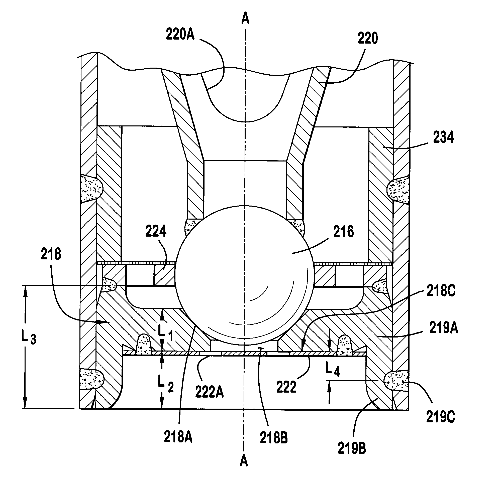
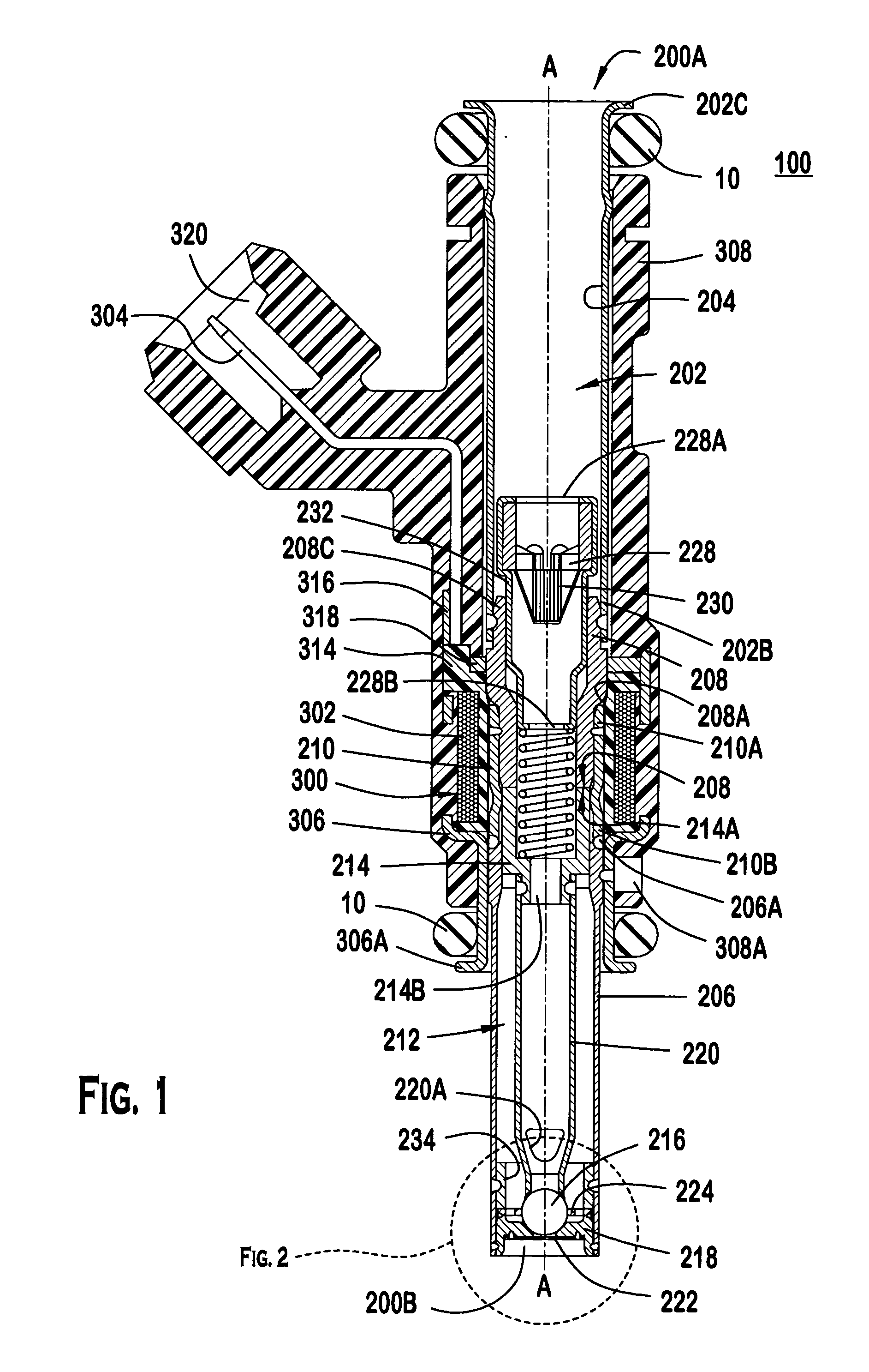
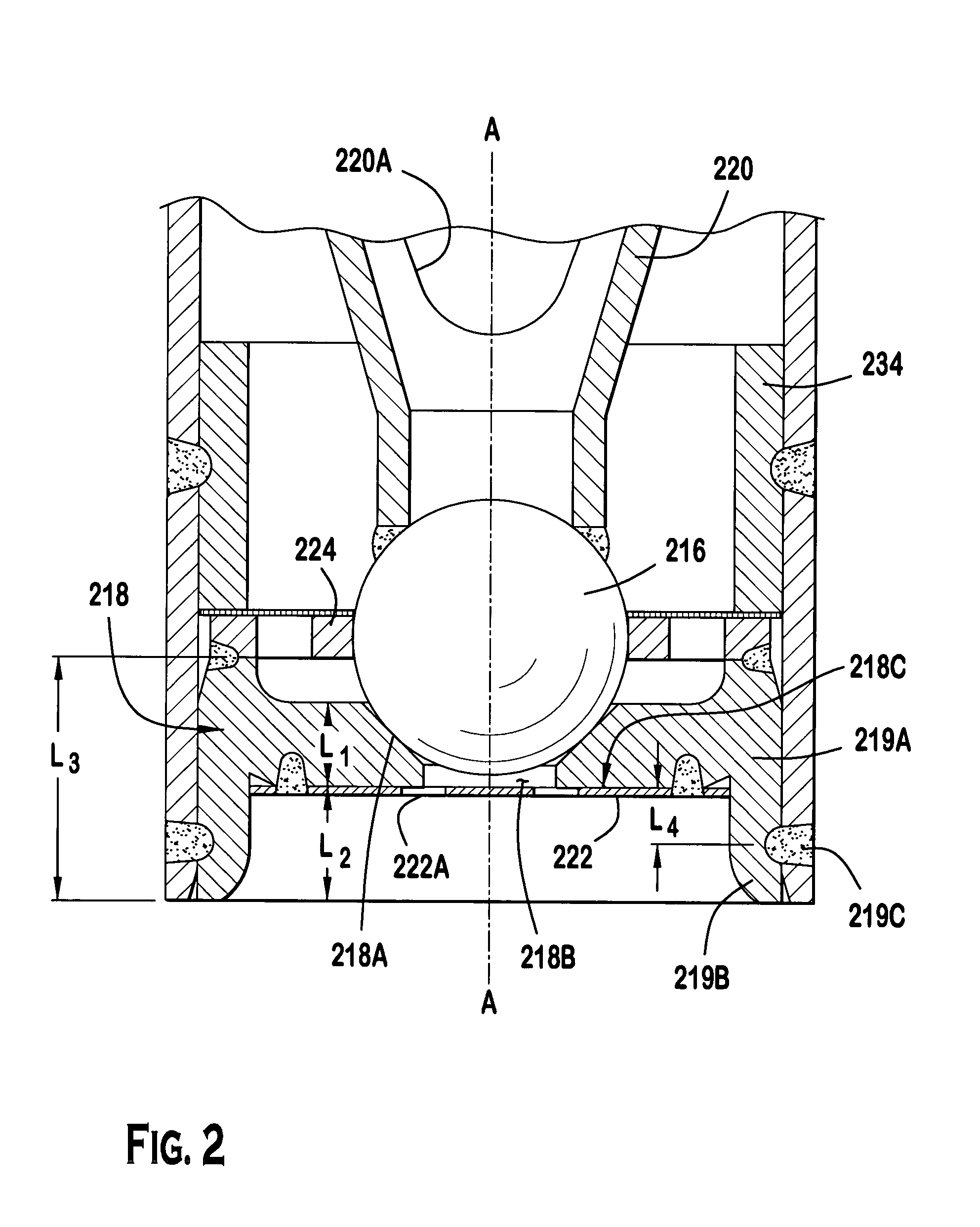
[0012] Referring to FIGS. 1 and 2, a solenoid actuated fuel injector 100 dispenses a quantity of fuel that is to be combusted in an internal combustion engine (not shown). The fuel injector 100 extends along a longitudinal axis between a first injector end 200A and a second injector end, and includes a valve group subassembly 200 and a power group subassembly 300. The valve group subassembly 200 performs fluid handling functions, e.g., defining a fuel flow path and prohibiting fuel flow through the injector 100. The power group subassembly 300 performs electrical functions, e.g., converting electrical signals to a driving force for permitting fuel flow through the injector 100.

[0013] The valve group subassembly 200 includes a tube assembly extending along the longitudinal axis A-A between a first tube assembly end 200A and a second tube assembly end 200B. The tube assembly 202 can include at least an inlet tube 204, a non-magnetic shell 210, and a valve body 206. The inlet tube 204...


PUM


Abstract

A modular fuel injector that includes a coil group subassembly and a valve group subassembly. The coil group subassembly is independently testable. The valve group subassembly is independently testable and includes a tube assembly having a longitudinal axis extending between a first tube end and a second tube end, and a seat assembly disposed in the tube assembly proximate the second tube end. The seat assembly includes a flow portion and a securement portion. The flow portion extends along the longitudinal axis between a first surface and an orifice disk retention surface at a first length. The flow portion has a seat orifice extending therethrough and an orifice disk coupled to the orifice disk retention surface so that the orifice plate is aligned in a fixed spatial orientation with respect to the flow portion. The securement portion extends along the longitudinal axis away from the orifice disk retention surface at a second length greater than the first length. A method of maintaining a fixed spatial orientation and dimensional symmetry of at least one of the seat and orifice disk in the valve subassembly is disclosed.

Description

BACKGROUND OF THE INVENTION [0001] It is believed that a seat of a conventional fuel injector can be attached to a valve body by placing the seat and an orifice disk within the valve body and crimping a terminal portion of the valve body to retain the seat and the orifice disk within the valve body. [0002] However, the crimping of the seat to the valve body may cause movement of the seat relative to a desired position in the valve body. Further, the seat, orifice disk, or the valve body may also distort at a location proximate the terminal end of the valve body. [0003] The change in seat location relative to the valve body may cause the working gap between an armature and a pole piece of the conventional fuel injector to be changed, thereby changing the desired flow rate. [0004] The distortion of the seat may cause the integrity of the sealing surface formed between a closure member and the seat to be changed, thereby potentially affecting emission due to leaks during a closed confi...

Claims


Application Information

Patent Timeline
Patent Type & Authority Applications(United States)
IPC IPC(8): F02M51/06F02M61/16F02M61/18F02M63/00
CPCF02M51/0682F02M61/165F02M2200/505F02M61/1853F02M61/168
Inventor DALLMEYER, MICHAEL P.IMOEHL, WILLIAM J.FOCHTMAN, JAMES P.BARNES, FREDRICK L.
Owner VITESCO TECH USA LLC
Why Eureka
Try Eureka