Directional coupler

a technology of directional couplers and couplers, applied in the field of directional couplers, can solve problems such as performance degradation sources, and achieve the effect of tight manufacturing tolerances

Active Publication Date: 2005-02-24
RPX CORP
View PDF12 Cites 40 Cited by
  • Summary
  • Abstract
  • Description
  • Claims
  • Application Information

AI Technical Summary

Benefits of technology

[0007] These and other objects that appear below are achieved by a directional coupler that uses non-metallic spacers connected through slots to the edges of a pair of broadside coupled lines. The spacers are adjustable in their position relative to the directional coupler housing, thereby providing continuous fine-adjustment of the gap between the lines, and hence of the coupling between the lines. The required spatial relationship between the coupled lines can therefore be achieved without extremely tight manufacturing tolerances.

Problems solved by technology

At the same time any metallic or non-metallic adjustment means for the coupled lines interfere with the electromagnetic fields around the lines and thereby become themselves a source of performance degradation.

Method used


Image

  • Directional coupler
  • Directional coupler
  • Directional coupler

Examples


first embodiment

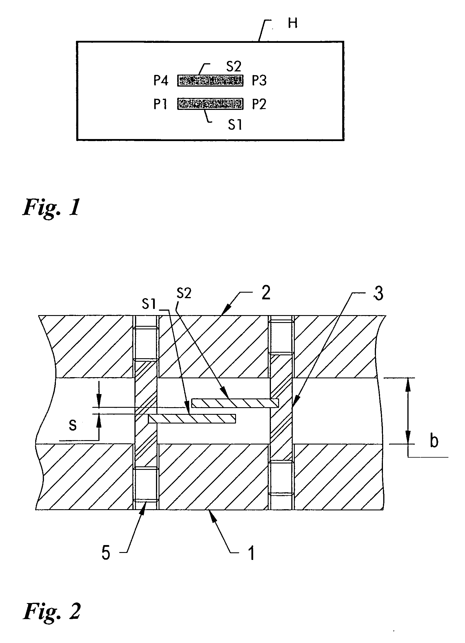
[0019]FIG. 2 shows a directional coupler according to the invention. It has first and second transmission lines S1, S2 arranged substantially parallel within a housing 1, 2 of the coupler. Each of the two transmission lines S1, S2 is fixedly attached to a corresponding non-metallic spacer 3, which is held in a corresponding hole in the housing. Set screws 5 allow to adjust the vertical position of each line within the housing and thereby adjust the gap s between the two lines. The spacers are attached through slots to the edges of the striplines. However other attachment means are likewise possible.

second embodiment

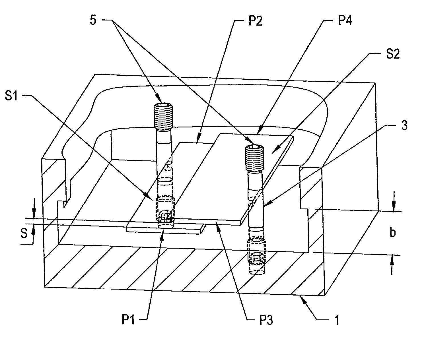
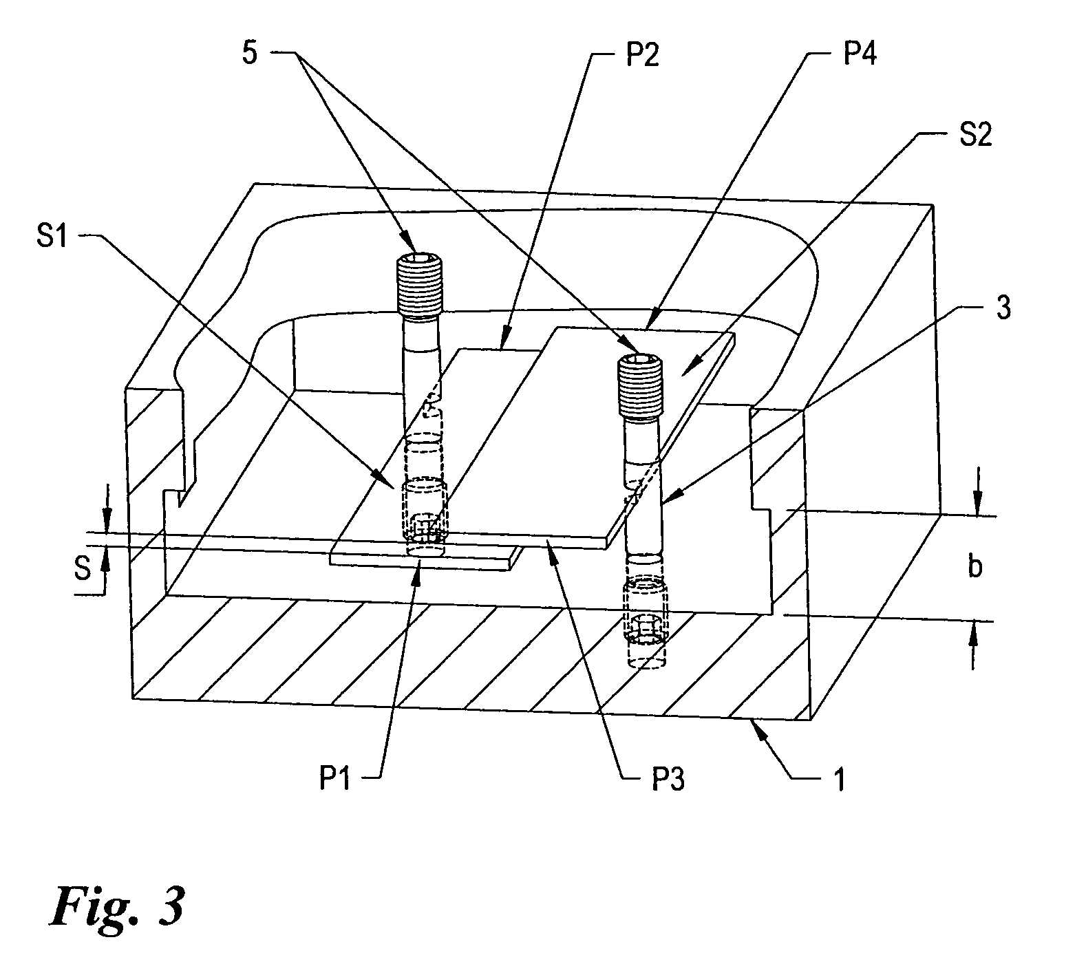
[0020]FIG. 3 shows in the invention inner details of a directional coupler with offset broadside-coupled striplines S1 and S2 arranged in a common housing 2. As in the embodiment before, each of the two transmission lines S1, S2 is fixedly attached to a corresponding non-metallic spacer 3, which is held in a corresponding hole in the housing 1. Set screws 5 allow to adjust the vertical position of each line within the housing 1 and thereby adjust the gap s between the two lines. Not shown in the figures are the port sections, where there is a departure from coupling to transmission, as these sections are not subject to the invention. The transmission sections may also provide further mechanical support for the striplines.

[0021] For ease of manufacture, parallelism is usually required and therefore, especially in broadband couplers with varying coupling along the line, the coupling is set by the amount of overlap between the lines (see FIG. 3) while the gap s between the lines is con...


PUM


Abstract

A directional coupler uses non-metallic slotted spacers at the edges of a pair of coupled lines. The spacers are adjustable in their vertical position and thereby provide continuous coupling fine-adjustment. The spatial relationship between the coupled lines is therefore adjustable and does not depend upon extremely tight manufacturing tolerances.

Description

[0001] The invention is based on a priority application EP 03291939.1 which is hereby incorporated by reference. FIELD OF THE INVENTION [0002] The present invention relates to the field of electronics and more particularly to a directional coupler using transverse-electromagnetic mode (TEM) transmission lines for high-frequency signals. BACKGROUND OF THE INVENTION [0003] The basic directional coupler is a linear, passive, four port network, incorporating two parallel coupled transmission lines. A first transmission line extends between an input port and a through port, and a second transmission line extends between a coupled port and an isolated port. A signal applied to the input port propagates along the first transmission line and induces a coupled signal into the second transmission line. In so-called backward-wave couplers, the coupled signal propagates in the reverse direction with reference to the transmission line to which the input signal is applied. [0004] A fundamental TE...

Claims


Application Information

Patent Timeline
Patent Type & Authority Applications(United States)
IPC IPC(8): H01P5/04H01P5/18
CPCH01P5/187H01P5/04
Inventor PELZ, DIETER
Owner RPX CORP
Why Eureka
Try Eureka