
Image processing apparatus, image processing method, and image processing program

a technology of image processing and image processing method, which is applied in the field of image processing apparatus, method and program, can solve problems such as the inability to display an image having realistic sensations

Inactive Publication Date: 2005-02-24
SONY CORP
View PDF16 Cites 44 Cited by
  • Summary
  • Abstract
  • Description
  • Claims
  • Application Information

AI Technical Summary

Benefits of technology

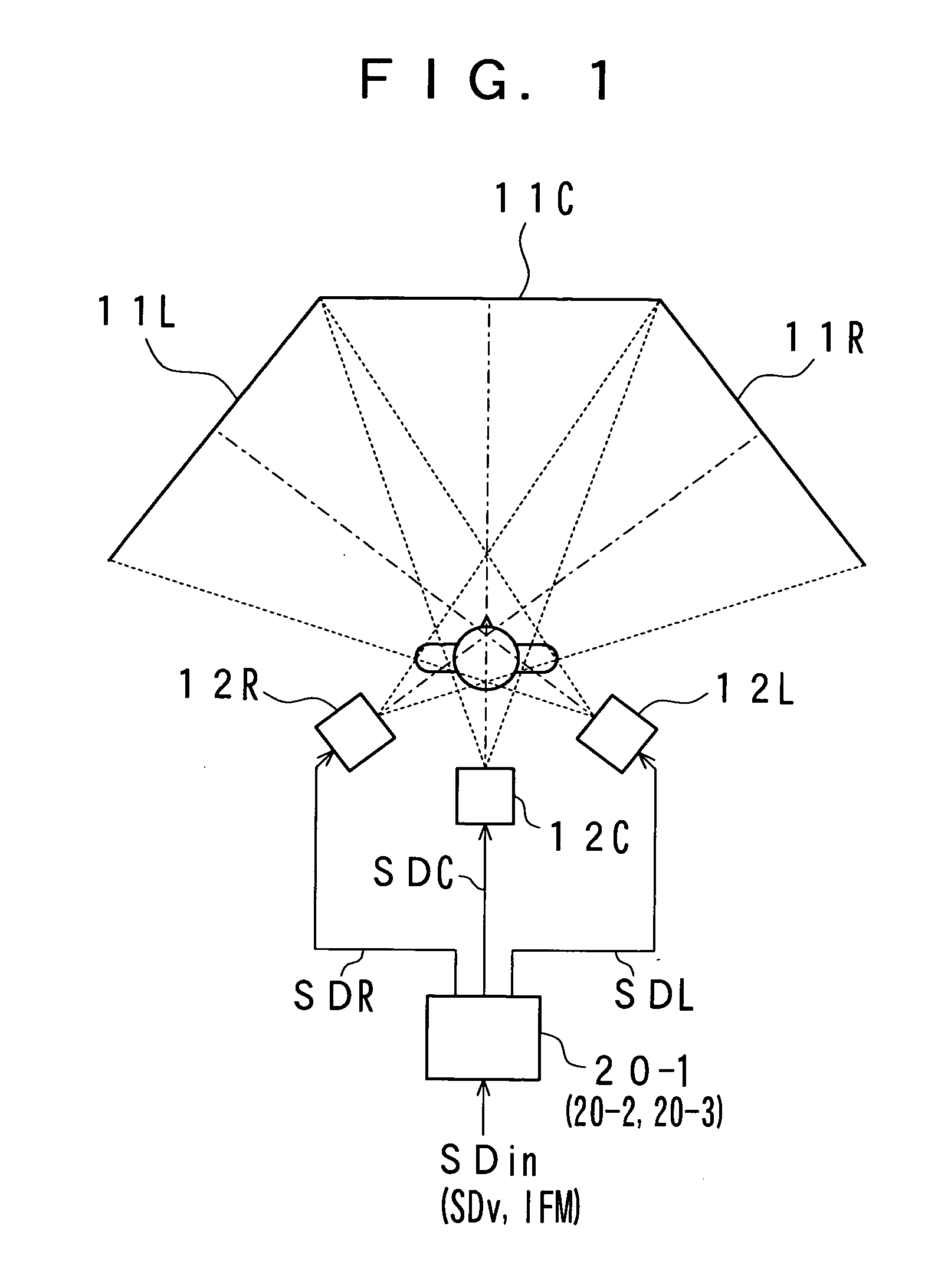
Further, a display position of the wide field angle image is slid on the basis of the movement in each of the images detected in the period of the continuous scene to prevent a portion of the received images in the display image from going out of an image display region and also, as this wide field angle image slides, a display position of each of the received images in the period of the continuous scene is corrected. Furthermore, in a case where the image display region in which the display image is displayed is comprised of multiple display regions, the display image is divided corresponding to the multiple display regions.

Problems solved by technology

Since the viewer feels as if he or she has moved owing to the movement of the background although he or she does not move actually, this feeling is accompanied by unnaturalness due to a mismatch with a real space, thus making it impossible to display an image having realistic sensations.

Method used


Image

  • Image processing apparatus, image processing method, and image processing program
  • Image processing apparatus, image processing method, and image processing program
  • Image processing apparatus, image processing method, and image processing program

Examples


first embodiment

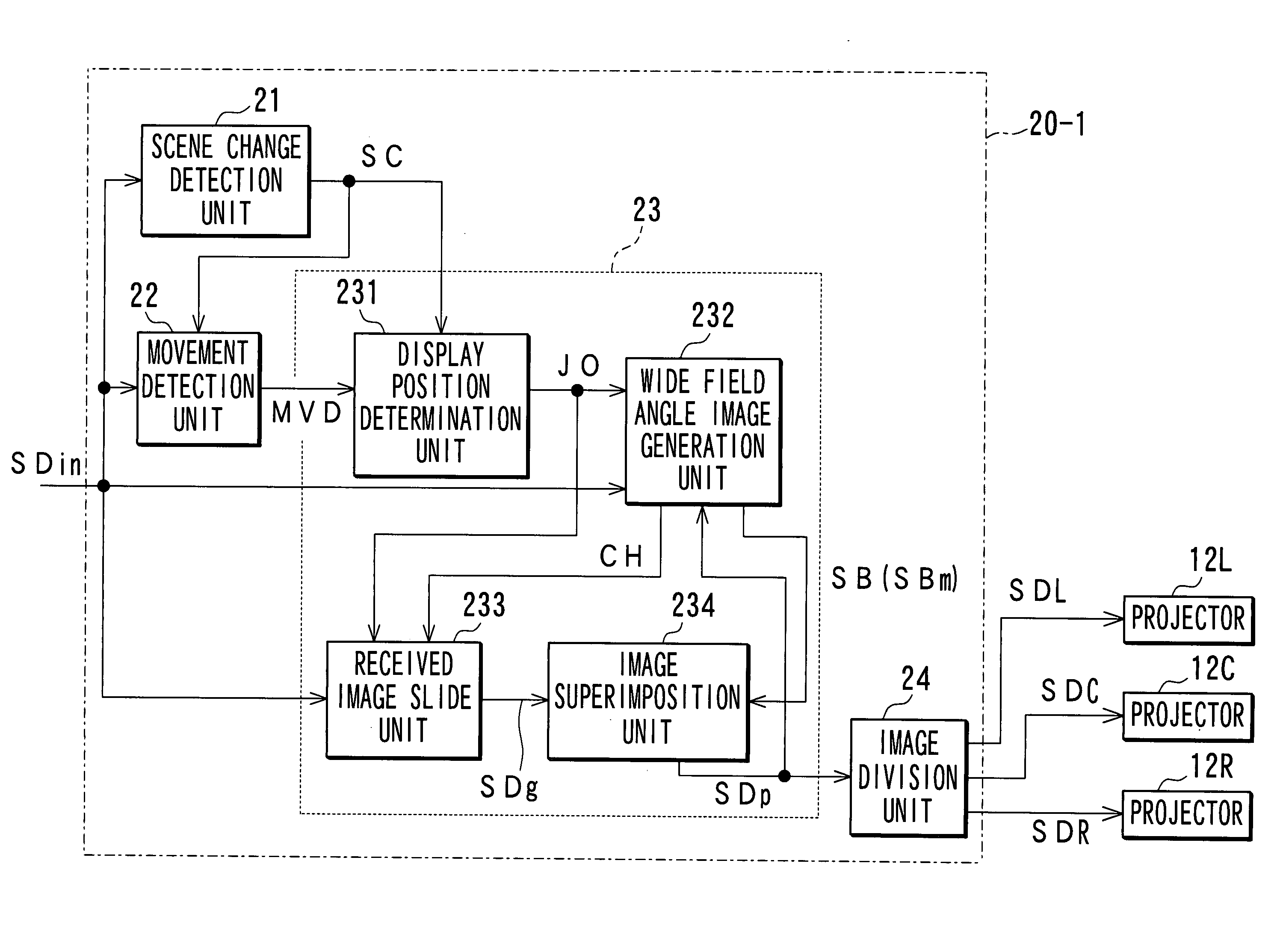
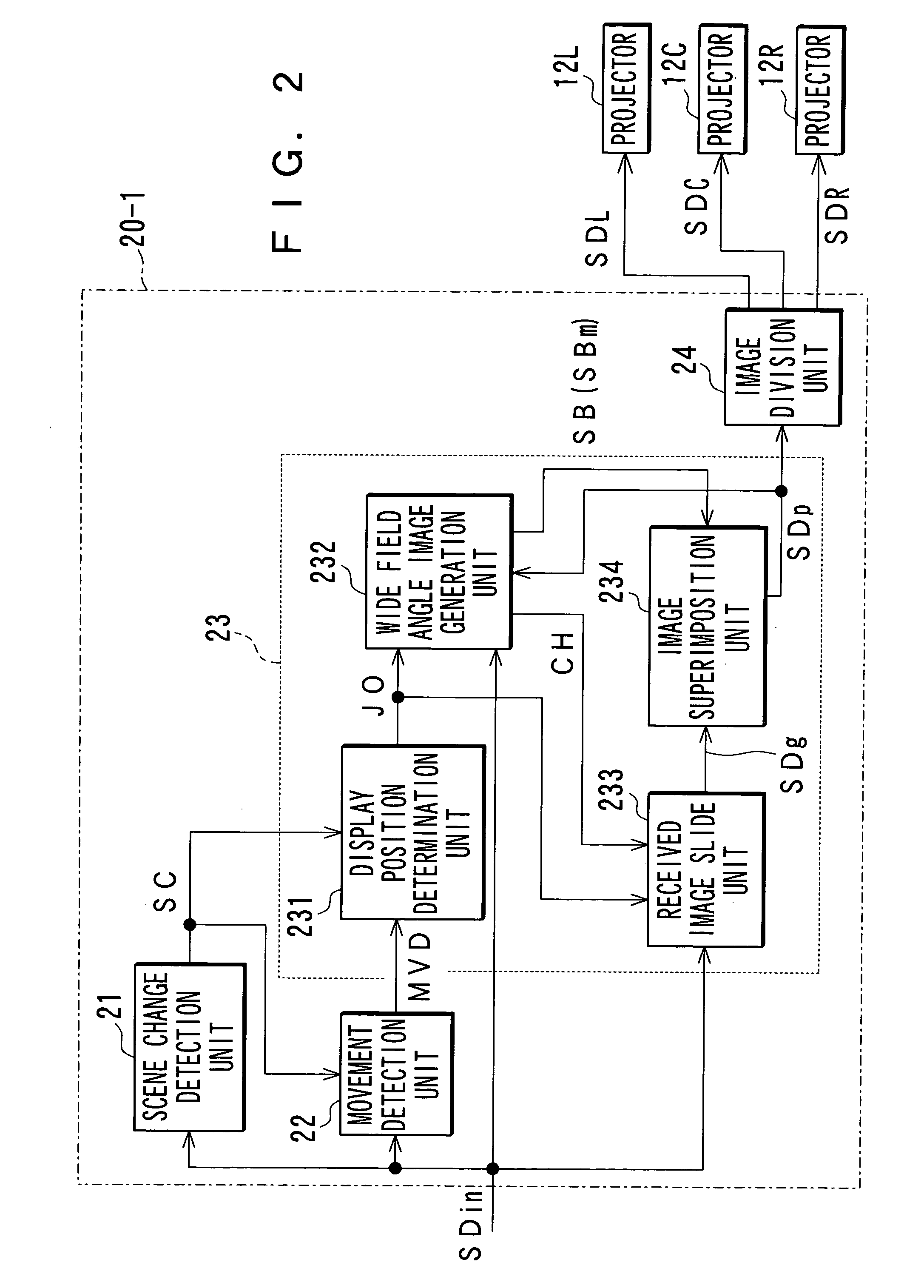
Next, a first embodiment is described with reference to a case where the image processing apparatus 20-1 is used. The image processing apparatus 20-1 decides a continuous scene by detecting scene change based on an image signal SDin of each received image. It sequentially uses the received images contained in the continuous scene thus decided, to detect a movement in an entire screen, thereby setting a display position of each of the received images based on the movement in the images obtained by the movement detection. Furthermore, it superimposes the received images at these set display positions in reverse order of time, to generate a wider field angle image than the received images. Further, based on the movement in the received images, it superimposes each of the received images on the wide field angle image so that an image of, for example, a background portion of each of the received images in which the movement has been detected may match the wide field angle image, thereby ...

second embodiment

It is to be noted that when images are sequentially displayed in a fixed image frame, unless switching of scenes in a display image is known properly, contents of a broadcast program, a movie, etc. cannot readily be understood in some cases. Further, if scene switching is performed frequently, it is difficult to know relevance between the scenes. Furthermore, unless the previous scene has been watched, contents of the subsequent scene cannot be understood in some cases. Therefore, the following will describe a case where an image processing apparatus 20-2 is used to perform image display that has realistic sensations and is easy to understand, as a

This image processing apparatus 20-2 detects scene change based on an image signal SDin of a received image to determine whether the scene change has been made and, based on a determined result, it switches an image display position for each of the scenes. Further, when switching the image display position, it displays such scenes as to h...

third embodiment

An image display system for projecting a shot large space onto a two-dimensional plane of a fixed image frame is accompanied with unnaturalness due to a mismatch with a real space because such a system expresses spatiality of the space and a movement in it utilizing sensory illusions of human beings. For example, when the subject is moving, a viewer cannot keep recognizing it unless he or she moves his or her viewpoint in line with the movement of the subject in the real space. However, in a conventional image display system, the viewer can keep recognizing the subject only by fixing his or her viewpoint position in the fixed image frame while in fact moving his or her viewpoint by sensory illusions, thus being accompanied by unnaturalness. Further, a program or a movie is produced on the assumption that various images are displayed in the fixed image frame, so that image expression power is deteriorated, thus disabling more realistic image display. Further, this holds true not only...


PUM


Abstract

Using an image signal SDin of a received image, a scene change detection unit 21 detects scene change of the received images. A movement detection unit 22 detects a movement in each of the received images. A display position determination unit 231 determines a display position of each of the received images based on the movement in each of the received images detected in a period of continuous scene. A wide field angle image generation unit superimposes the received images in said period of said continuous scene, a display position of which has been determined, to generate an image signal SB of the wide field angle image. A received image slide unit 233 generates image signal SDg wherein the received images are slid to the display positions. An image superimposition unit 234 superimposes the received images whose display positions have been slid on the wide field angle image, to generate an image signal SDp of a wide field angle display image in which the display position of each of the received images is slid in response to the movement in each of the received images.

Description

TECHNICAL FIELD The present invention relates to an image processing apparatus, method, and program. BACKGROUND ART Conventionally, in an image display system for displaying an image of a TV broadcasting program, a movie, etc., the image has been displayed using one fixed image frame such as a display screen of a TV set, a movie screen, etc. Image contents of a broadcast program, a movie, etc. have also been made on the assumption that the image is to be displayed using such a fixed image frame. Furthermore, recently, in order to enhance realistic sensations in image display, a multi-screen display system and such displays as a curved-surface display, a wide field angle display, and a head-mount display have been made practicable. However, even when such a multi-screen display system and the like are utilized, a contents-production has been realized on the assumption that related images are displayed in such a manner as to match the fixed screen frame using a image display region...

Claims


Application Information

Patent Timeline
Patent Type & Authority Applications(United States)
IPC IPC(8): H04N5/14H04N5/74H04N9/12
CPCH04N5/145H04N9/3147H04N9/12H04N5/147H04N5/66G09G5/36G09G5/377
Inventor KONDO, TETSUJIROKIKUCHI, DAISUKE
Owner SONY CORP
Learn More