Neon light using a rope light as a light source

a rope light and neon light technology, applied in the field of neon light, can solve the problems of poor waterproof capability of the conventional neon light, inconvenient assembly of the device, and the possibility of seeping moisture on the circuit board (b>3/b>), so as to increase the waterproof capability of the neon light and reduce the maintenance fee

Inactive Publication Date: 2005-02-24
FAN BEN
View PDF8 Cites 32 Cited by
  • Summary
  • Abstract
  • Description
  • Claims
  • Application Information

AI Technical Summary

Benefits of technology

[0007] The primary objective of the present invention is to provide an improved neon light to greatly reduce the maintenance fee and increase the waterproof capability of the neon light.
[0008] Another objective of the present invention is that a rope light is received in a milky colored U-shaped cover so that the light from the rope light after passing through the milky colored U-shaped cover is soft.
[0010] A further objective of the present invention is that the rope light has a milky colored gel injection molded outside each one of the LEDs so that the waterproof capability of the neon light of the present invention is high.

Problems solved by technology

However, because the connection between the tube (1) and the supporting bracket (2), the end caps (4) and the tube (1) and the circuit board (3) and the tube (1) arc glued together, waterproof capability of the conventional neon light is poor and the circuit board (3) is very possible to be damaged by the seeping moisture.
What is more important is that after they are glued together, the assembly of the device becomes quite inconvenient.
That is, they all have the same problem of high production and maintenance fee.
However, due to the consideration of easy assembly of the transparent tube, the waterproof capability is thus sacrificed.
Furthermore, the application of the circuit board increases the manufacture cost.

Method used


Image

  • Neon light using a rope light as a light source
  • Neon light using a rope light as a light source
  • Neon light using a rope light as a light source

Examples


Embodiment Construction

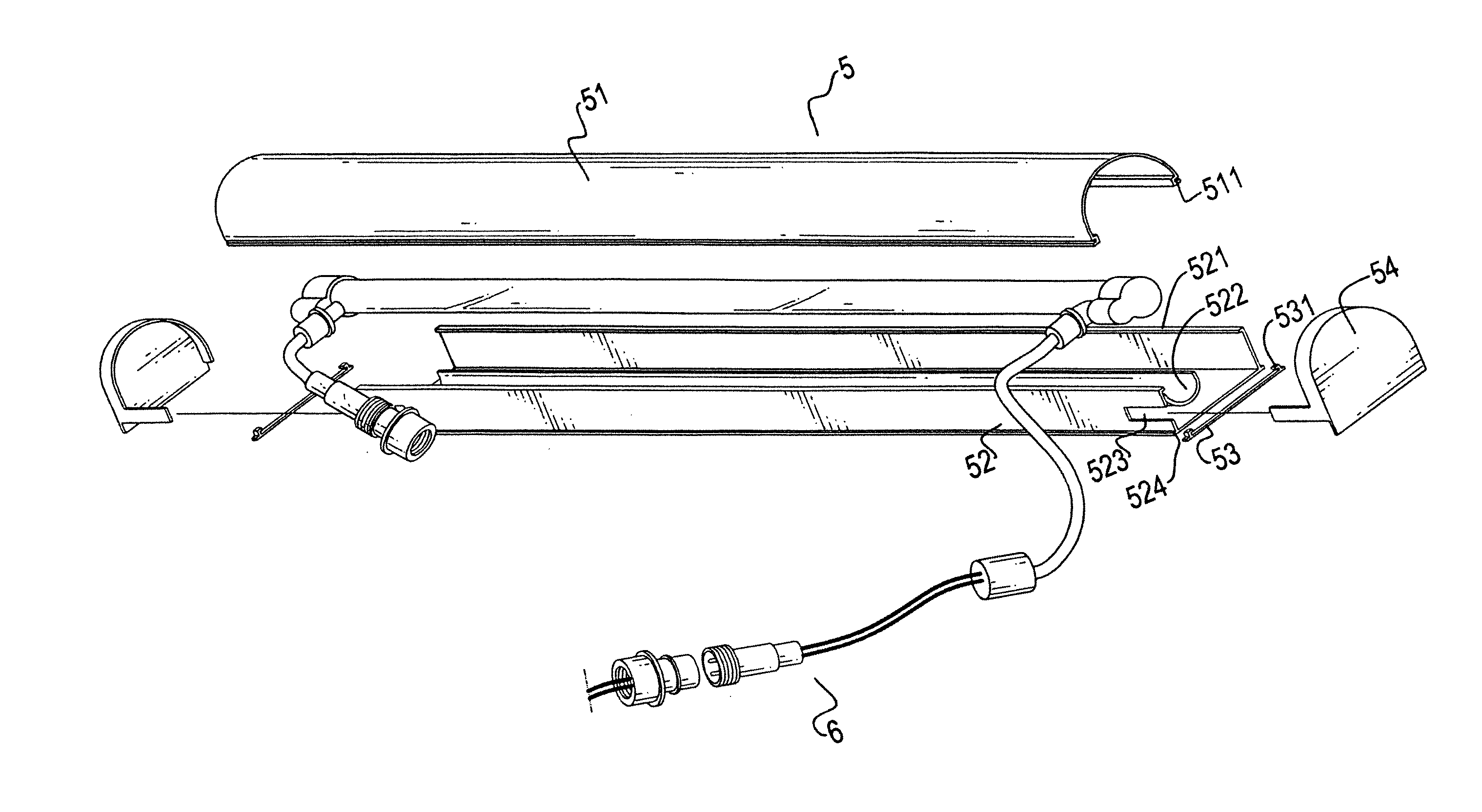
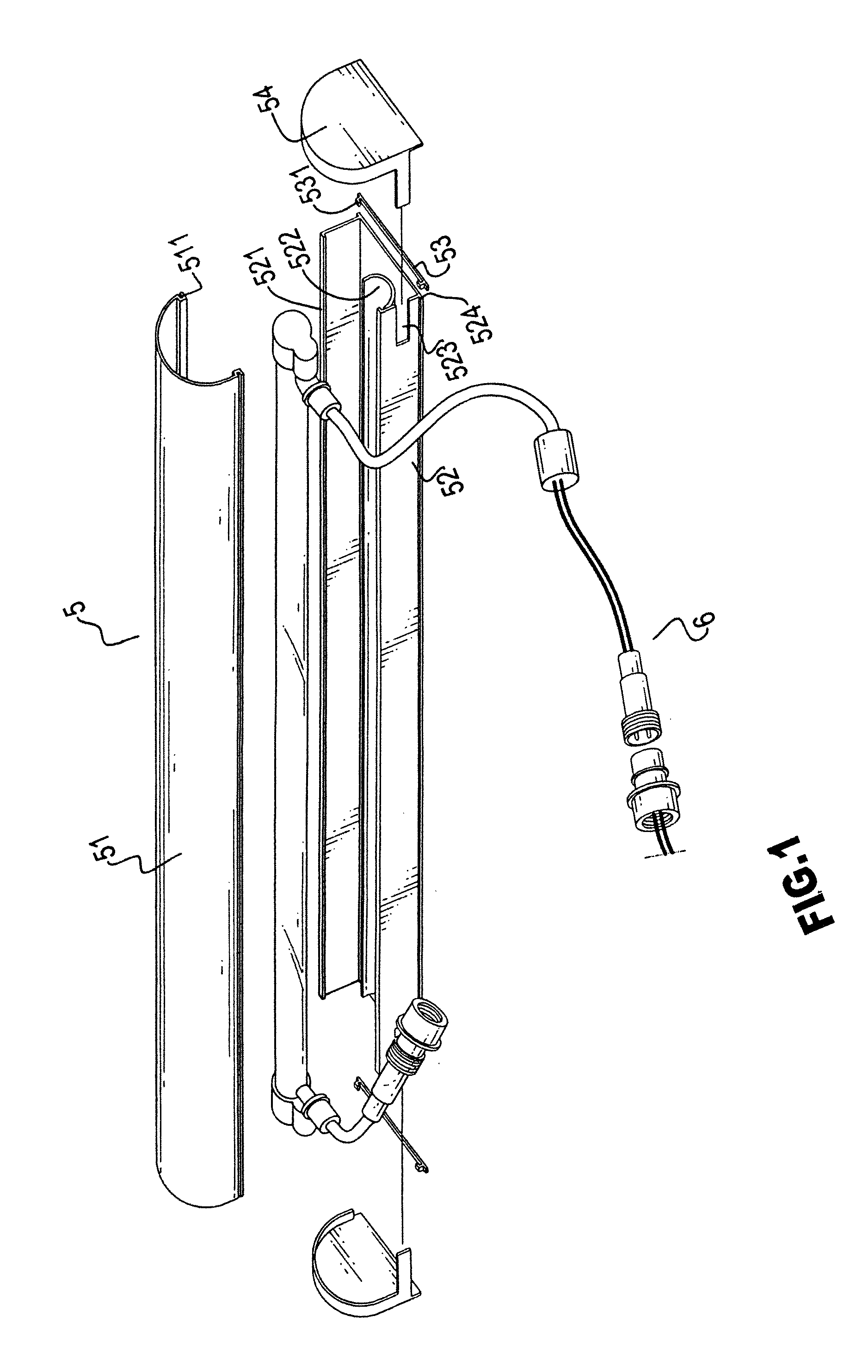
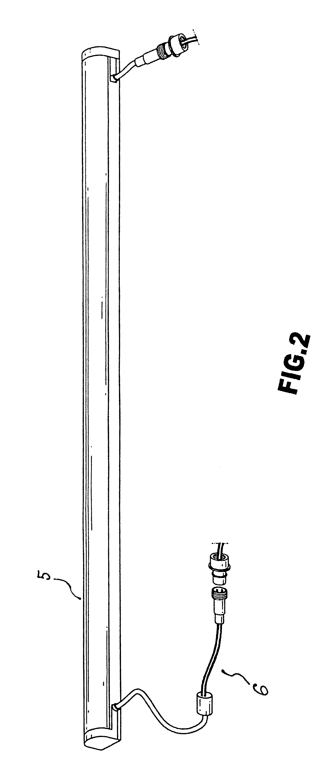
[0018] With reference to FIGS. 1 and 2, the neon light in accordance with the present invention includes a cover (5) and a rope light (6).

[0019] The cover (5) is composed of a translucent U-shaped cover (51) and a base (52) corresponding and connected to a bottom of the U-shaped cover (51). A ledge (511) is formed on two longitudinal sides of the U-shaped cover (51). A rib (521) is formed on two longitudinal free sides of the two side wails of the base (52) to correspond to the ledge (511). The two side walls (not numbered) are respectively perpendicularly extended from a bottom face of the base (52) and an arcuate seat (522) is longitudinally formed between the two side walls of the base (52). One of the two side walls has two cutouts (523) oppositely defined in two distal ends of the side wall. A recess (524) is formed on a joint of each of the two side walls and the bottom face of the base (52) to correspond to a positioning element (53). The positioning element (53) has two ext...


PUM


Abstract

A neon light includes a cover and a rope light. The cover is composed of a milky colored U-shaped cover and a base connected to the U-shaped cover. A ledge is formed on two free sides of the U-shaped cover to correspond to two ribs formed on two upright side walls on a top face of the base. An arcuate seat is formed between the two side walls to receive thereon the rope light. Two end caps are provided to seal two open ends defined by combination between the U-shaped cover and the base.

Description

BACKGROUND OF THE INVENTION [0001] 1. Field of the Invention [0002] The present invention relates to a neon light, and more particularly to a neon light having therein a rope light as a light source to emit light such that the waterproof capability of the neon light is improved. [0003] 2. Description of Related Art [0004] With reference FIG. 6, a conventional neon light has a transparent or translucent tube (1), a supporting bracket (2) having the tube (1) thereon, a circuit board (3) received in the tube (1) and two end caps (4) to end cap two open ends of the tube (1) to prevent water from seeping into the tube (1) to damage the circuit board (3). The circuit board (3) has multiple light emitting diodes (31) (LED) mounted thereon so that when the LED (301) are lit, the light from the LED (301) is able to pass through the transparent or translucent tube (1) to emanate a soft light. Because the material for the tube (1) is milky colored and the LED (301) can be arranged to emit diff...

Claims


Application Information

Patent Timeline
Patent Type & Authority Applications(United States)
IPC IPC(8): F21S4/00F21V15/01F21V23/06
CPCF21S4/007F21S4/008F21V15/01F21Y2103/003F21V23/06F21V31/005F21Y2101/02F21V23/008F21S4/26F21S4/28F21Y2103/10F21Y2115/10
Inventor FAN, BEN
Owner FAN BEN
Why Eureka
Try Eureka