
Lighting device for vehicle

a technology for lighting devices and vehicles, applied in the direction of lighting support devices, fixed installations, lighting and heating apparatus, etc., can solve the problem of insufficient irradiation of light in a great transverse inclined direction to the front of the lighting devi

Inactive Publication Date: 2005-02-24
KOITO MFG CO LTD
View PDF6 Cites 39 Cited by
  • Summary
  • Abstract
  • Description
  • Claims
  • Application Information

AI Technical Summary

Benefits of technology

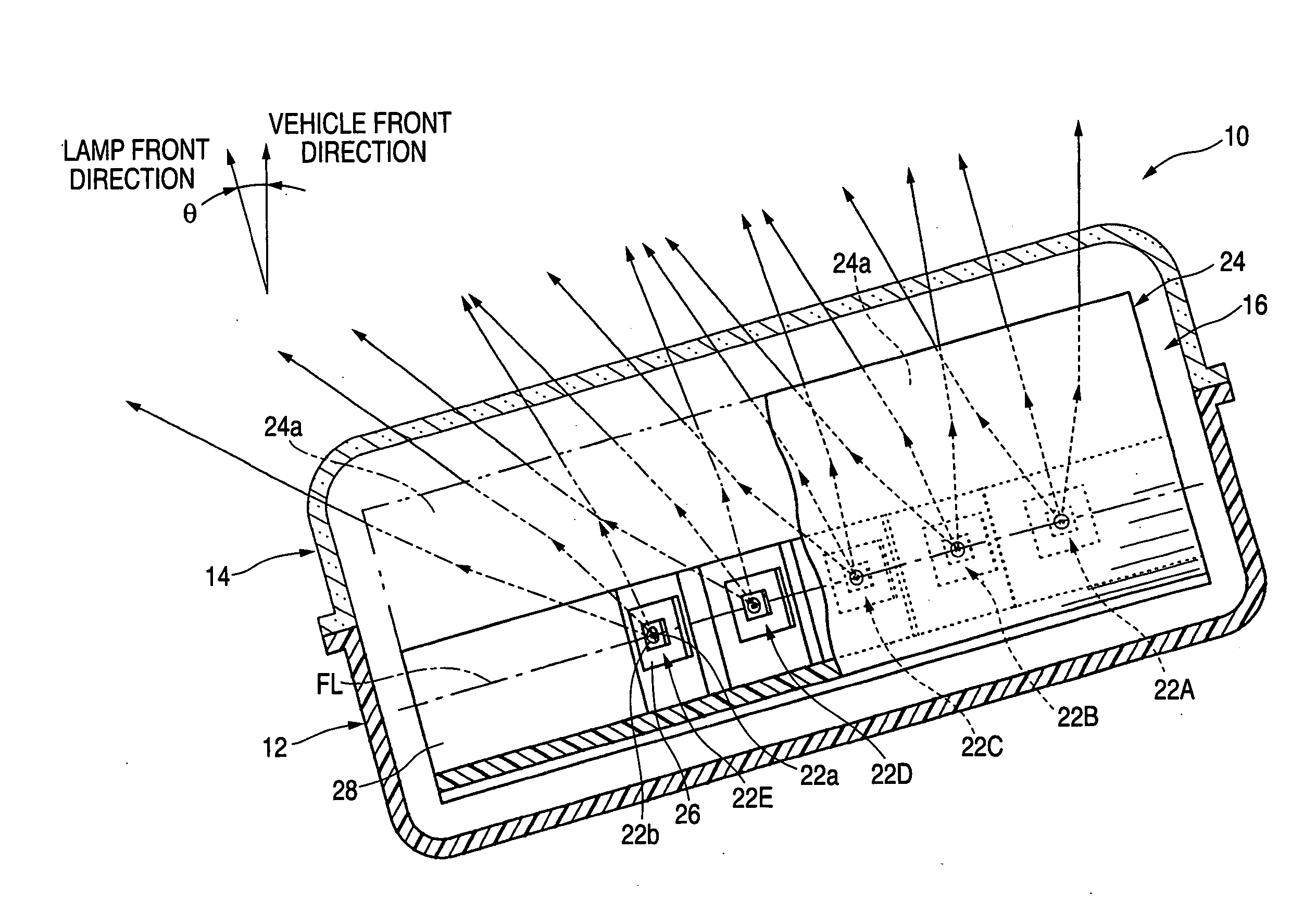
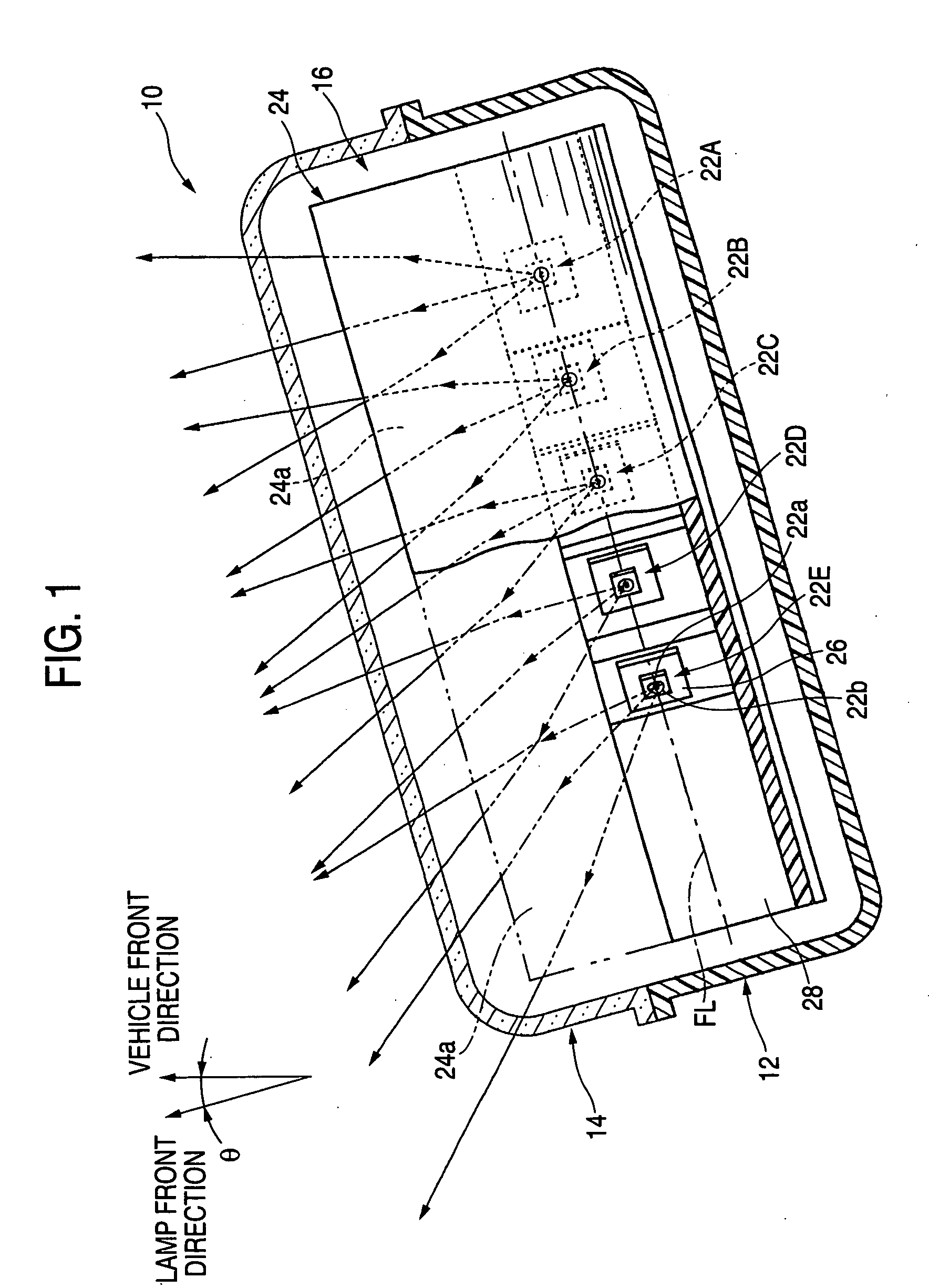
[0010] More specifically, an exemplary, non-limiting embodiment of the invention provides a lighting device for a vehicle, which is constituted to reflect lights emitted from a plurality of semiconductor light emitting devices toward a forward part of the lighting device by means of a reflector, wherein a reflecting surface of the reflector is constituted by a parabolic cylindrical curved surface having a focal line extended in a horizontal direction, and the semiconductor light emitting devices are provided on the focal line at a predetermined interval, and a direction of a light emitted from at least one of the semiconductor light emitting devices is set to be different from directions of the other semiconductor light-emitting devices with respect to a direction of the focal line.
[0010] More specifically, an exemplary, non-limiting embodiment of the invention provides a lighting device for a vehicle, which is constituted to reflect lights emitted from a plurality of semiconductor light emitting devices toward a forward part of the lighting device by means of a reflector, wherein a reflecting surface of the reflector is constituted by a parabolic cylindrical curved surface having a focal line extended in a horizontal direction, and the semiconductor light emitting devices are provided on the focal line at a predetermined interval, and a direction of a light emitted from at least one of the semiconductor light emitting devices is set to be different from directions of the other semiconductor light-emitting devices with respect to a direction of the focal line.
[0010] More specifically, an exemplary, non-limiting embodiment of the invention provides a lighting device for a vehicle, which is constituted to reflect lights emitted from a plurality of semiconductor light emitting devices toward a forward part of the lighting device by means of a reflector, wherein a reflecting surface of the reflector is constituted by a parabolic cylindrical curved surface having a focal line extended in a horizontal direction, and the semiconductor light emitting devices are provided on the focal line at a predetermined interval, and a direction of a light emitted from at least one of the semiconductor light emitting devices is set to be different from directions of the other semiconductor light-emitting devices with respect to a direction of the focal line.

Problems solved by technology

However, there is a related art problem in that it is impossible to sufficiently irradiate light in a great transverse inclined direction to the direction of the front of the lighting device.

Method used


Image

  • Lighting device for vehicle
  • Lighting device for vehicle
  • Lighting device for vehicle

Examples


Embodiment Construction

[0025] An embodiment of the invention will be described below with reference to the drawings.

[0026]FIG. 1 is a sectional plan view showing a lighting device for a vehicle according to an exemplary, non-limiting embodiment of the present invention. A lighting device 10 for a vehicle is a cornering lamp to be provided on the left and front end of the vehicle, and irradiates a light on a forward part in a turning direction when the vehicle turns. In the lighting device 10, a lighting unit 16 is accommodated in a lamp housing formed by a lamp body 12 and a translucent cover 14 attached to an opening portion on a front end thereof, and the direction of the front is inclined at a predetermined angle θ (for example, θ=15°) leftward with respect to the direction of the front of the vehicle.

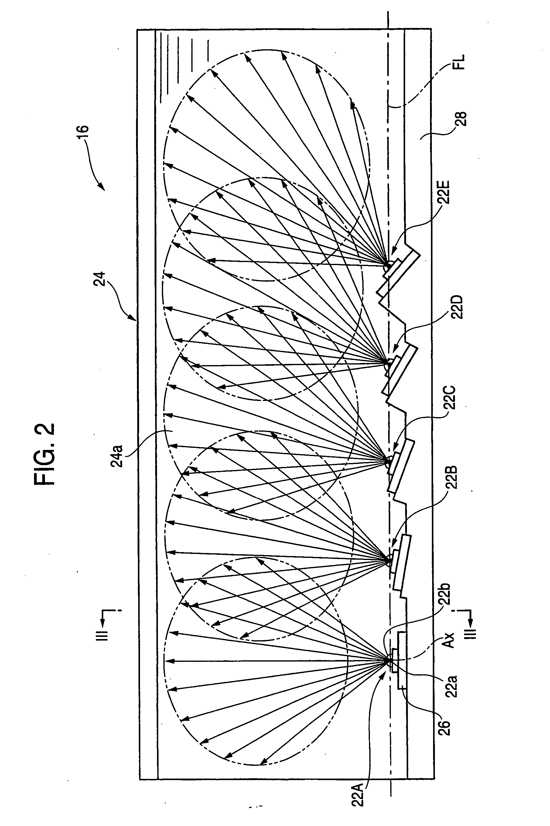
[0027]FIG. 2 is a view showing the lighting unit 16 seen in the direction of the front of the lighting device and FIG. 3 is a sectional view taken along a III-III line in FIG. 2. The lighting unit 16 re...


PUM


Abstract

For light irradiation transversely inclined with respect to the front of a vehicle lighting device that reflects light from a plurality of semiconductor light emitting devices toward the forward part of the lighting device via reflector, a structure is provided in which lights emitted from five semiconductor light emitting devices are reflected toward the forward part of a lighting device via reflector. A reflecting surface of the reflector is a parabolic cylindrical curved surface having a focal line extended horizontally. The five semiconductor light emitting devices are on the focal line at an interval. Each of the directions of the emitted lights is varied for each semiconductor light emitting device with respect to the focal line direction. Consequently, the light emitted from each of the semiconductor light emitting devices is not diffused vertically but only horizontally, thereby forming five oblong light distribution patterns in positions shifted from each other horizontally.

Description

[0001] The present application claims priority under 35 USC 119 based on Japanese Patent Application No. 2003-286883, filed Aug. 5, 2003, the contents of which is incorporated herein by reference. BACKGROUND OF THE INVENTION [0002] 1. Technical Field [0003] The present invention relates to a lighting device for a vehicle that reflect lights emitted from a plurality of semiconductor light emitting devices toward the forward part of the lighting device by a reflector. [0004] 2. Related Art [0005] As described in Japanese patent application JP-A-11-306810, for example, a related art lighting device for a vehicle reflects lights from a plurality of semiconductor light emitting devices toward the forward part of the lighting device by means of a reflector. [0006] Moreover, Japanese patent application JP-A-2003-31007 has described a related art vehicle lighting device that reflects lights from a plurality of semiconductor light emitting devices arranged rectilinearly in a horizontal direc...

Claims


Application Information

Patent Timeline
Patent Type & Authority Applications(United States)
IPC IPC(8): B60Q1/12B60Q1/04B60Q1/18F21S8/10F21V5/04F21V14/02F21V19/00F21W107/10F21Y101/02
CPCB60Q1/12B60Q1/18B60Q2300/122B60Q2300/142F21Y2105/005F21S48/1747F21S48/215F21S48/218F21Y2101/02F21S48/1159F21Y2115/10F21Y2107/50F21S41/147F21S41/663F21S43/14F21S43/15F21S41/148F21S41/151B60Q2900/40B60Q1/04F21V5/04
Inventor ISHIDA, HIROYUKI
Owner KOITO MFG CO LTD
Learn More