Information recording medium

Inactive Publication Date: 2003-05-01
RICOH KK
View PDF21 Cites 67 Cited by
  • Summary
  • Abstract
  • Description
  • Claims
  • Application Information

AI Technical Summary

Problems solved by technology

However, applying the materials with those compositions to optical recording medium for high density recor

Method used


Image

  • Information recording medium
  • Information recording medium
  • Information recording medium

Examples


example 1

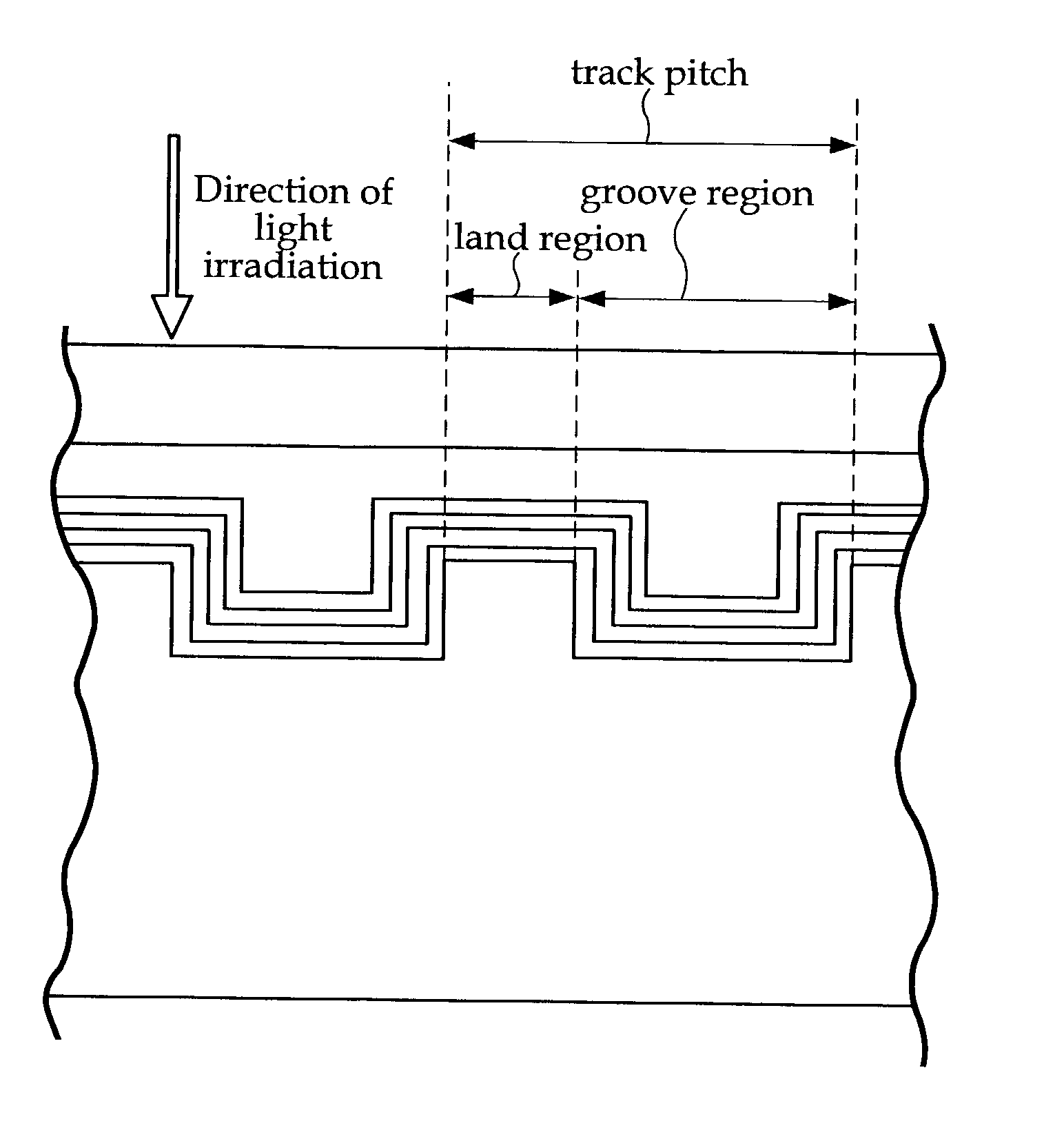
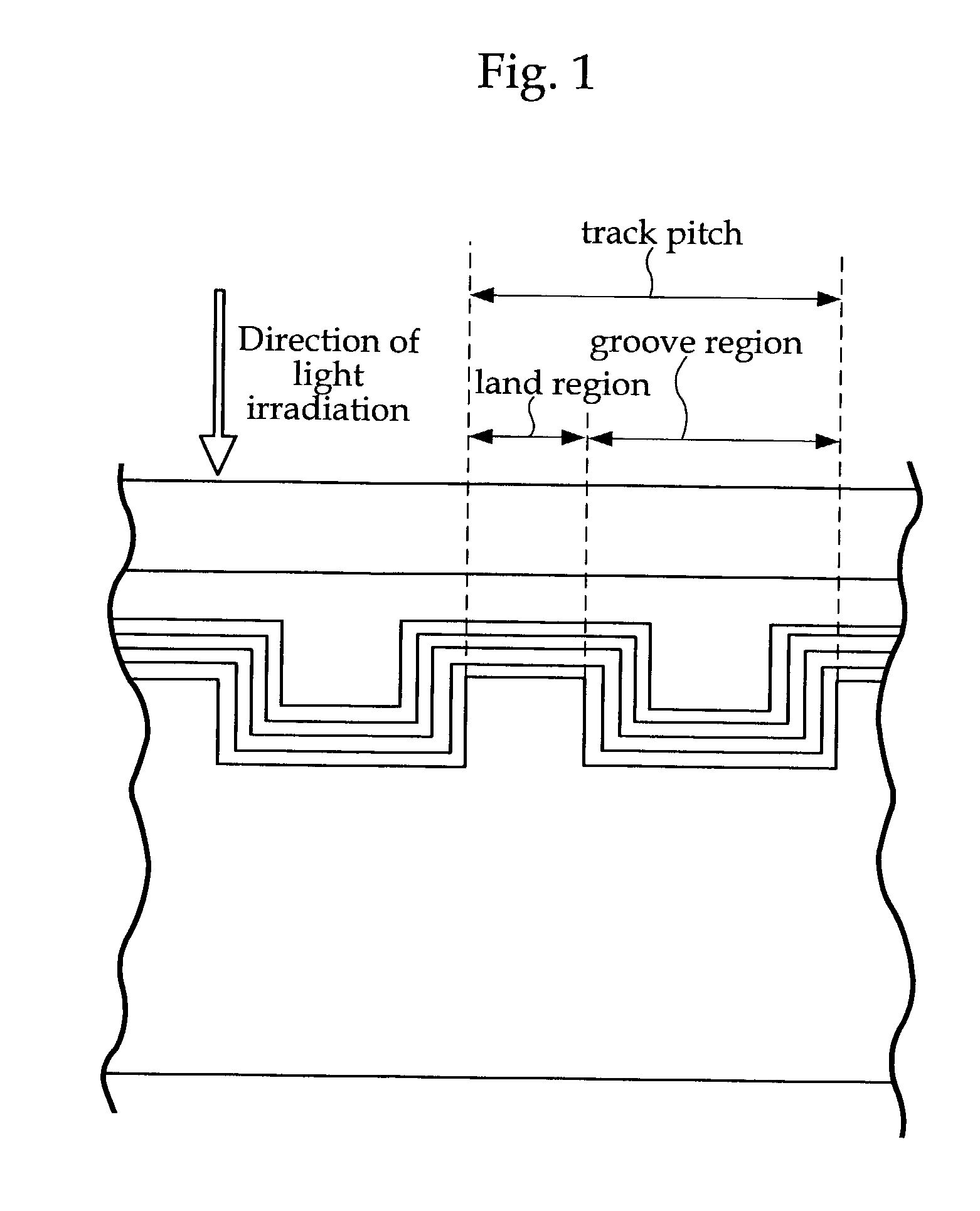
[0124] Setting the track pitch at 0.32 .mu.m, and a ratio at 0.46 (the value in which the average groove width 0.15 is divided by the track pitch 0.32), on a 1.1 mm thick disk-shaped polycarbonate substrate having 120 mm diameter, the layers were formed in the following order, by using sheet sputtering equipment: 120 nm thick light reflection layer (AgCu), 5 nm first protection layer comprising AlN, 12 nm thick (ZnS--SiO.sub.2), 12 nm thick recording layer (Ag.sub.1In.sub.3Sb.sub.70Te.sub.23Ge.sub.3), and 120 nm thick second protection layer (ZnS--SiO.sub.2). In addition, a 60 .mu.m polycarbonate cover layer was formed by a modified acrylic adhesive (a product of NittoDenko Co., Ltd., the brand name DA8310-A50), and a 1 .mu.m thick layer was formed as the hard coating on the injection side of the disk (a product of Mitsubishi Rayon Co., Ltd. under the brand name MH7617N), obtaining the phase change optical disk according to the present invention with a final thickness of 1.2 mm. FIG...

example 2

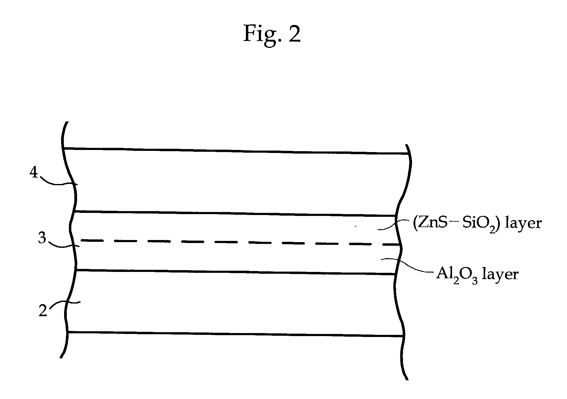
[0130] Setting the track pitch at 0.33 .mu.m, and a ratio at 0.45 (the value in which the average groove width 0.15 is divided by the track pitch 0.33), on a 1.1 mm thick disk-shaped polycarbonate substrate having 120 mm diameter, the layers were formed in the following order, by using sheet sputtering equipment: 140 nm thick light reflection layer (AgPdCu), 5 nm thick first protection layer comprising Al.sub.2O.sub.3, and 12 nm thick first protection layer (ZnS--SiO.sub.2), and 120 nm thick second protection layer (ZnS--SiO.sub.2). In addition, a 70 .mu.m polycarbonate cover layer was formed by a modified acrylic adhesive (a product of NittoDenko Co., Ltd., the brand name DA8310-A50), and a 1 .mu.m thick layer was formed as the hard coating on the injection side of the disk (a product of Mitsubishi Rayon Co., Ltd. under the brand name MH7617N), which resulted in obtaining the phase change optical disk according to the present invention with a final thickness of 1.2 mm. FIG. 1 shows...

example 3

[0136] Setting the track pitch at 0.33 .mu.m, and a ratio at 0.45 (the value in which the average groove width 0.15 is divided by the track pitch 0.33), on a 1.1 mm thick disk-shaped polycarbonate substrate having 120 mm diameter, the layers were formed in the following order, by using sheet sputtering equipment: a 140 nm thick light reflection layer (AgPdCu), a 5 nm thick first protection layer comprising Ta.sub.2O.sub.5, and a 12 nm thick first protection layer (ZnS--SiO.sub.2), and 120 nm thick second protection layer (ZnS--SiO.sub.2). In addition, a 70 .mu.m polycarbonate cover layer was formed by a modified acrylic adhesive (a product of NittoDenko Co., Ltd., the brand name DA8310-A50), and a 1 .mu.m thick layer was formed as the hard coating on the injection side of the disk (a product of Mitsubishi Rayon Co., Ltd. under the brand name MH7617N), which resulted in obtaining the phase change optical disk according to the present invention with a final thickness of 1.2 mm. FIG. 1...


PUM


Abstract

An optical recording medium configured with a light reflection layer; a first protection layer; a recording layer containing a phase-change material which changes between crystalline and amorphous phases by a light irradiation; a second protection layer; and one of a cover layer and a protective coating layer disposed on a substrate in this order; and in which the light reflection layer is formed of one of an Al alloy and an Ag alloy; the first protection layer has a ZnS-SiO2 mixture layer which contains a mixture of ZnS and SiO2, and a intermediate layer having higher thermal conductivity than the ZnS-SiO2 mixture layer; the intermediate layer is formed on the side of the light reflection layer; the recording layer comprises Ge, Sb, and Te as main elements; and the second protection layer comprises a mixture of ZnS and SiO2.

Description

[0001] 1. Field of the Invention[0002] The present invention relates to an optical recording medium such as a rewritable DVR, comprising a phase-change recording layer for high density recording.[0003] 2. Description of the Related Art[0004] In general, recording of a binary signal and detecting of tracking signal in a compact disc (CD) or DVD is carried out utilizing a change of reflectivity caused by interference of reflected light from the bottom of a concave pit as well as a mirror finished surface. Recently, phase-change rewritable compact disc (CD-RW, or CD-Rewritable) has been generally used as the medium compatible with CD. Moreover, regarding DVD, various types of phase-change rewritable DVD have been proposed. Furthermore, it is proposed that the wavelength for recording and reproducing be shortened to 390 nm to 420 nm for a DVD capacity of 4.7 GB, which leads to increasing the numerical aperture (NA) and to realizing a DVR with the capacity of 20 GB or more (Refer to page...

Claims


Application Information

Patent Timeline
IPC IPC(8): G11B7/0045G11B7/24G11B7/243G11B7/254G11B7/257G11B7/258
CPCG11B7/00454Y10S430/146G11B7/24038G11B7/243G11B7/2534G11B7/254G11B7/2542G11B7/257G11B7/258G11B7/2585G11B7/259G11B2007/24312G11B2007/24314G11B2007/24316G11B7/24
Inventor SHINOTSUKA, MICHIAKI
Owner RICOH KK
Why Eureka
Try Eureka