Light emitting source and a light emitting source array

a technology of light emitting sources and arrays, applied in the field of light emitting sources and light emitting source arrays, can solve the problems of giving up any thickness, uniformity, power consumption, and creating a backlight that is thinner, and achieves uniform light intensity distribution and color mixing, good color reproducibility, and low power consumption.

Inactive Publication Date: 2008-07-15
ORMON CORP
View PDF6 Cites 68 Cited by
  • Summary
  • Abstract
  • Description
  • Claims
  • Application Information

AI Technical Summary

Benefits of technology

[0018]As described above, in the conventional backlights, the backlight using LEDs of three colors, namely, red, green, and blue were good in color reproducibility. However, in the backlight using the LEDs of three colors, the equalizing space expanded, which forced us to give up any of thickness, uniformity, and power consumption, and did not allow us to create a backlight that is thinner, and has uniform light intensity distribution and color mixing as well as low power consumption.
[0019]One or more embodiments of the present invention lies (lie) in provision of a light emitting source array using light emitting device, such as LED, etc. that has uniform light intensity (illuminance) on an illuminated surface (when a plurality of light emitting devices are included, in particular, color mixing should be uniform), is thinner, and has low power consumption. It further lies in provision of a light emitting source for use in the light emitting source array, a lighting system or a liquid crystal display system that is used in the light emitting source array.

Problems solved by technology

However, in the backlight using the LEDs of three colors, the equalizing space expanded, which forced us to give up any of thickness, uniformity, and power consumption, and did not allow us to create a backlight that is thinner, and has uniform light intensity distribution and color mixing as well as low power consumption.

Method used


Image

  • Light emitting source and a light emitting source array
  • Light emitting source and a light emitting source array
  • Light emitting source and a light emitting source array

Examples


embodiment 1

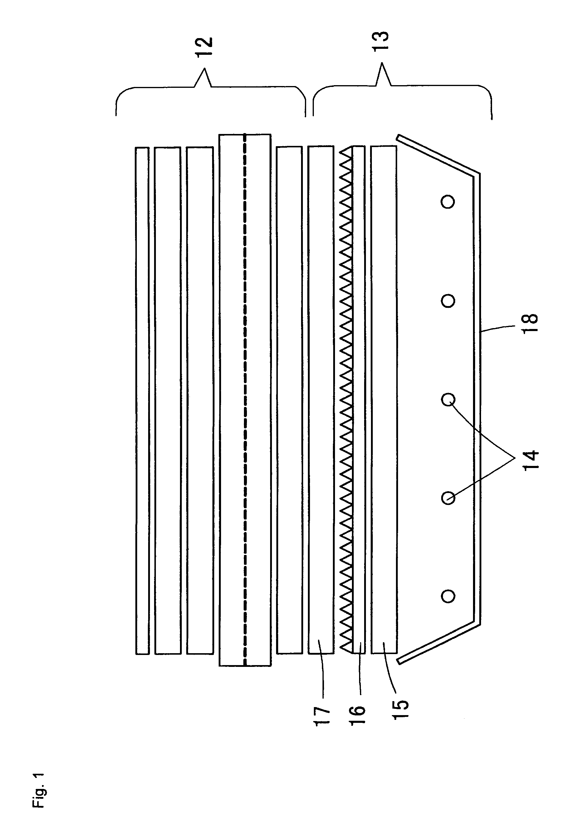
[0088]FIG. 9 shows the schematic sectional view illustrating the structure of a liquid crystal display (liquid crystal display system) 41 according to Embodiment 1 of the present invention. The liquid crystal display 41 is configured with a backlight 43 positioned on the rear of a liquid crystal panel 42. The liquid crystal panel 42 may be of a general type, and is comprised of a polarizing plate 44, a liquid crystal cell 45, a phase difference plate 46, a polarizing plate 47 and an antireflection film 48 that are sequentially laminated from the back face.

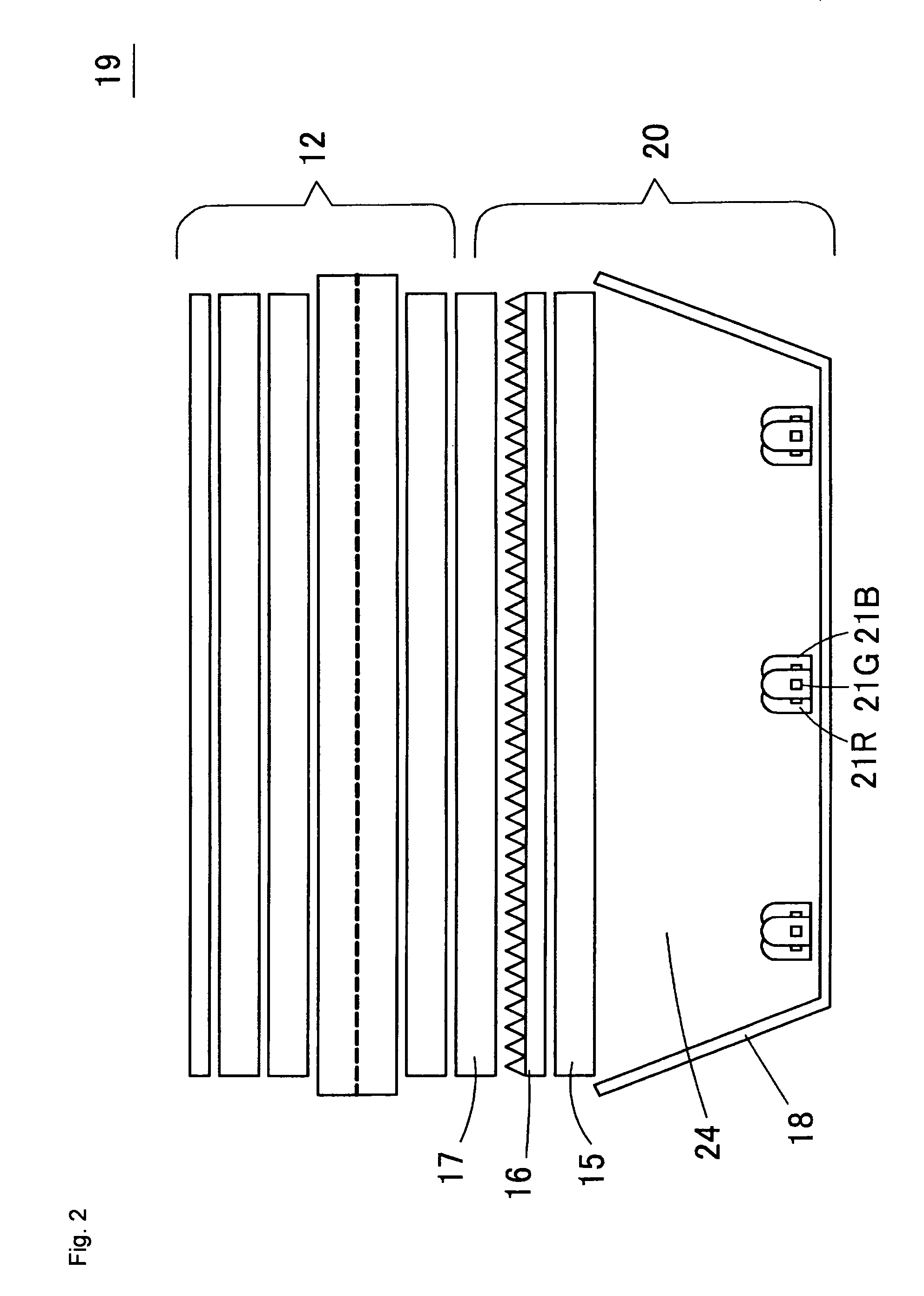
[0089]The backlight 43 is such configured that a light diffusing film 51, a prism sheet 52, and brightness enhancing film 53 are positioned on the front of light emitting source array 50 on which a plurality of light emitting sources 49 are arranged. As described below, the light emitting sources 49 are formed like a square when viewed from a front view, and the light emitting source array 50 is comprised of the said light emitting...

embodiment 2

[0115]FIG. 21 shows a sectional view of a light emitting source 68 according to Embodiment 2 of the present invention and a partial enlarged view thereof. In the light emitting source 68, toric channel 58 is depressed and installed between the direct output area 60 and the total reflection area 61, thus forming a slope total reflection area 63 along the sides of the inner circumference of the channel 58. In addition, a conically shaped depression 66 is depressed and installed in the central part of the direct output area 60, forming a slope total reflection area 67 on the outer circumference of the depression 66.

[0116]Thus, in the Embodiment 2, among light outputted from the light emitting devices 56R, 56G, and 56B, light entering the inner slope total reflection area 67 is total reflected sequentially at 3 points of the slope total reflection area 67, the direct output area 60, and the outer slope total reflection area 63. Then, the light total reflected at the slope total reflecti...

embodiment 3

[0118]Fit. 22 shows a sectional view of a light emitting source 69 in the diagonal direction according to Embodiment 3 of the present invention. Although the light emitting source 69 has almost similar structure to Embodiment 1, a direct output area 60 is gently inclined, thus being conically shaped. In the light emitting source 69, similar to Embodiment 1, light outputted from the light emitting devices 56R, 56G, and 56B to the slope total reflection area 63 is total reflected at the slope total reflection area 63, entering the direct output area 60. Then, after being total reflected in the direct output area 60 and reflected at the direct output area 60, the light enters the reflecting area 64d either by being total reflected at the total reflection area 61 or directly, is reflected at the reflecting area 64d, and outputted from the corner part of the light emitting source 69.

[0119]Thus, even in such the embodiment, distribution of intensity of the light outputted from the light e...


PUM


Abstract

On the rear surface of a transparent molded unit is provided a reflecting member. In a central part of the molded unit are encapsulated light emitting devices. In the vicinity of the central part of the reflecting member is formed a reflecting area that is angularly inclined to the rear surface as it moves to the outer circumferential direction. A toric channel is provided on a light irradiation surface of the molded unit, and a slope total reflection area is provided in its inner circumferential side. Light emanating from the light emitting devices is reflected at the slope total reflection area, and further reflected at the direct output area. Then, after being further reflected at the reflecting area of the reflecting member, the light is guided to the outer circumferential end of the reflecting member, and is outputted forward from the total reflection area by being reflected at the outer circumferential end of the reflecting member.

Description

FIELD OF THE INVENTION[0001]The present invention relates to a light emitting source and a light emitting source array. The invention further relates to a lighting system or a liquid crystal display system, etc. that uses a light emitting source array.DESCRIPTION OF THE RELATED ART[0002]In recent years, as a representative of flat-screen televisions, a liquid crystal display television (LCD television) has gradually come into widespread use. A liquid crystal panel used in LCD televisions generates an image by transmitting or shielding light for every picture element. However, as the liquid crystal panel is not capable of emitting light by itself, it needs to have a backlight (surface light source system). As more of LCD televisions being manufactured are wide-screen type, a backlight for LCD televisions is required to have a large area luminescent surface, and high brightness that is uniform a cross the screen. In the following, we describe a conventional liquid crystal display or a...

Claims


Application Information

Patent Timeline
Patent Type & Authority Patents(United States)
IPC IPC(8): F21V7/04H01L33/54H01L33/60H01L33/62
CPCG02B6/0001G02B17/086G02F1/133603G02B6/0031H01L33/58H01L33/60H01L2224/48091H01L2924/3025H01L2924/1815H01L2224/48247H01L2924/00014H01L2924/00G02F1/1335
Inventor AYABE, TAKAHIROMATSUI, AKIRAHOMMA, KENJIKIYOMOTO, HIRONOBU
Owner ORMON CORP
Why Eureka
Try Eureka