Spectral characteristic obtaining apparatus, image evaluation apparatus and image forming apparatus

a technology of image evaluation and obtaining apparatus, applied in the direction of spectrometry/spectrophotometry/monochromator, optical radiation measurement, instruments, etc., can solve the problem of inability to measure the spectral characteristic of the same position of the object to be inspected, error in comparison with the reference or estimation of continuous spectral characteristics,

Inactive Publication Date: 2011-12-08
RICOH KK
View PDF16 Cites 68 Cited by
  • Summary
  • Abstract
  • Description
  • Claims
  • Application Information

AI Technical Summary

Benefits of technology

[0016]Embodiments of the present invention may provide a novel and useful spectral characteristic obtaining apparatus,...

Problems solved by technology

Therefore, if a different position is selected as an object to be inspected in each of the images, an error would occur in comparison with the reference or estimation of the continuous spectral characteristic.
However, the technique does not include a measure that reduces the position gap of the images obtained at each of the wavelength bands.
The technique disclosed in Patent Document 2 uses a configuration that obtains the reflected light from the object to be inspected by the continuous irradiation light from the light source with different wavelength bands, but it is impossible for the configuration to measure the spectral characteristic of the same position of the object to be inspected because of occurrence of time lag.
The technique disclosed in Patent Document 3 also has had a configuration ...

Method used


Image

  • Spectral characteristic obtaining apparatus, image evaluation apparatus and image forming apparatus
  • Spectral characteristic obtaining apparatus, image evaluation apparatus and image forming apparatus
  • Spectral characteristic obtaining apparatus, image evaluation apparatus and image forming apparatus

Examples


first embodiment

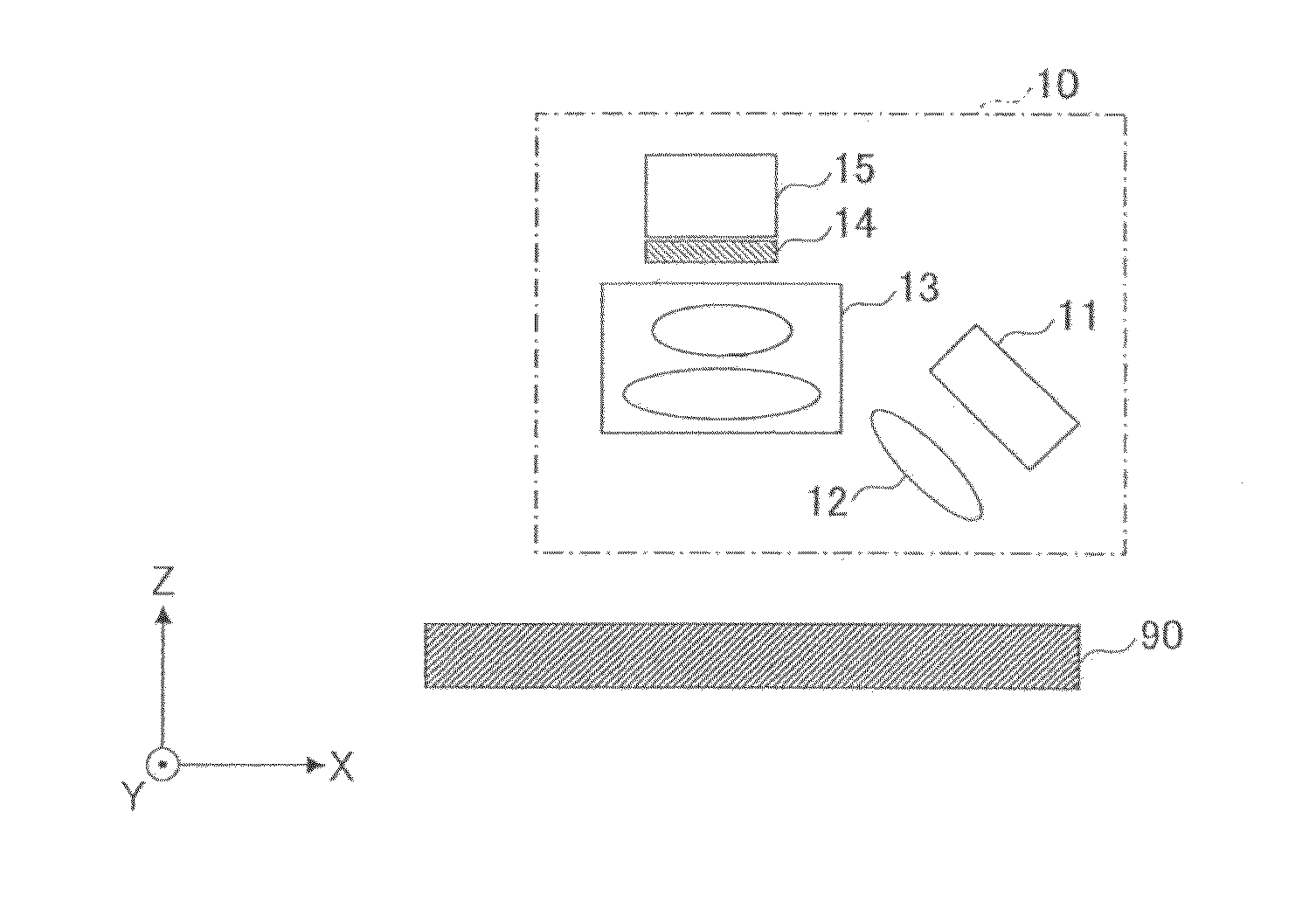
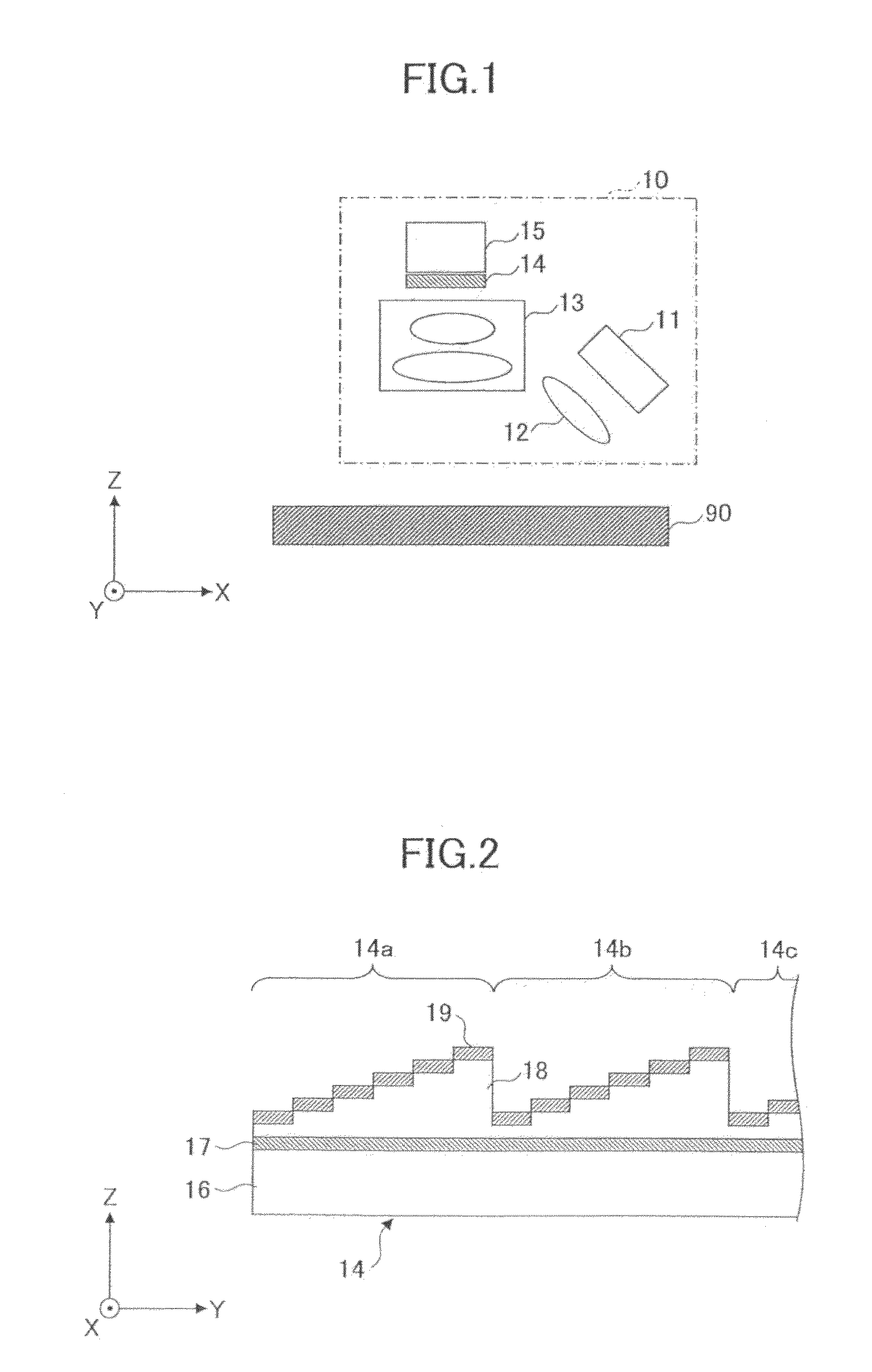
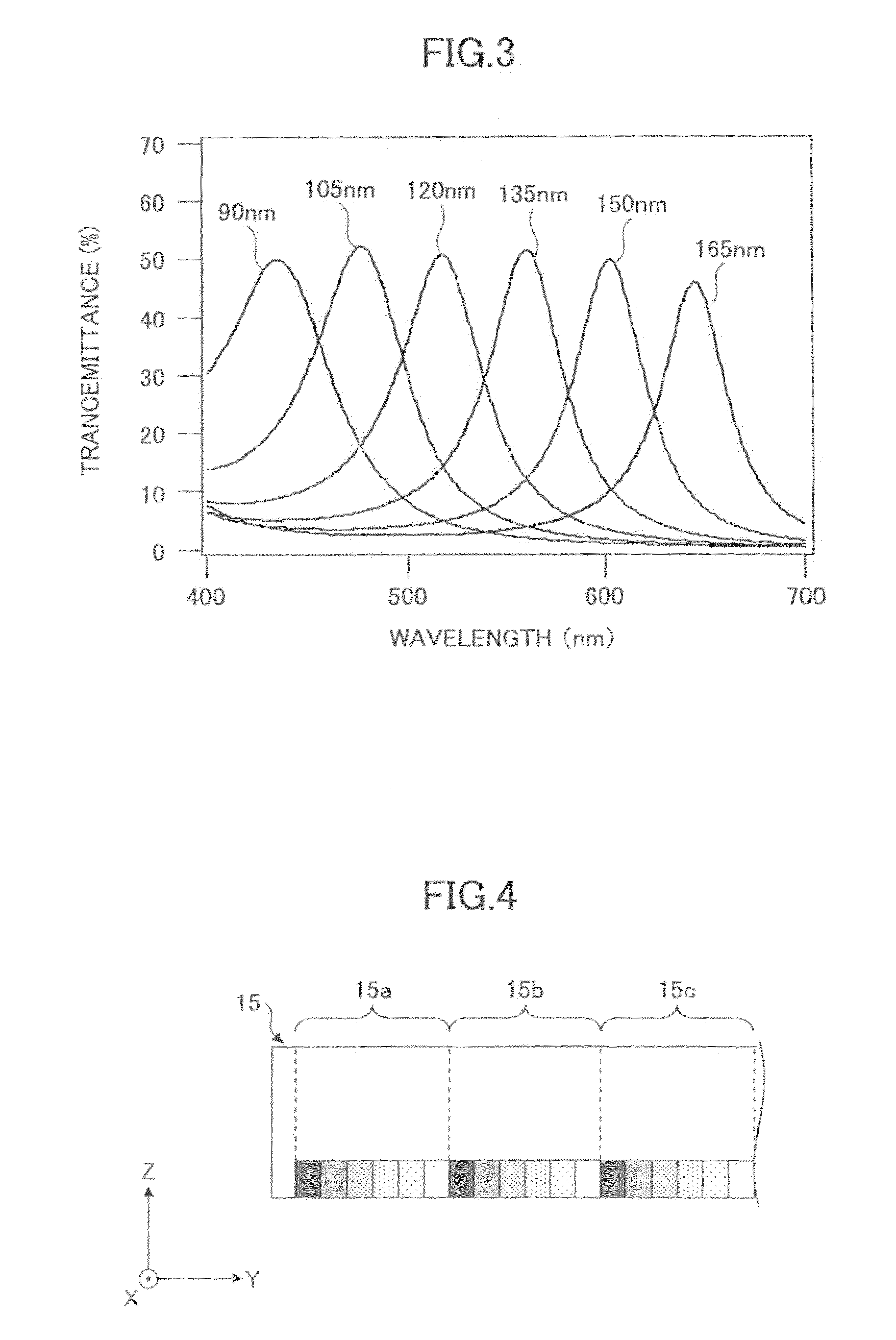
[0087]FIG. 1 is a diagram illustrating a spectral characteristic obtaining apparatus of a first embodiment. Referring to FIG. 1, the spectral characteristic obtaining apparatus includes a line illumination light source 11, a collimating lens 12, an imaging optical system 13, a filter array 14, and a line sensor 15. An image holding medium (e.g., paper and the like) 90 is also shown in FIG. 1.

[0088]The line illumination light source 11 has a function to emit light. As the line illumination light source 11, for example, a white LED (i.e., Light Emitting Diode) array that has intensity of light in almost all ranges of visible light are available. As the line illumination light source 11, a fluorescent light such as a cold-cathode tube and a lamp light source are also available. Here, the line illumination light source 11 is desirable to emit light in a wavelength range necessary for dispersion, and to be able to homogeneously illuminate an entire observation area. The collimated lens 1...

second embodiment

[0102]In the first embodiment, since the imaging optical system 13 forms an image on the line sensor 15 from the image on the image holding medium 90 as shown in FIG. 1, each of the N pixels constituting one spectroscopic sensor (e.g., spectroscopic sensor 15a) receives light from different positions on the image holding medium 90. This does not cause problems when the image on the image holding medium 90 has a rougher structure than a pixel structure. However, if the image has a similar fine structure compared to the pixel structure, obtaining an exact spectral characteristic of the measurement object becomes difficult because the plural pixels constituting the spectroscopic sensor (e.g., spectroscopic sensor 15a) form different images respectively. Accordingly, in a second embodiment, in order to solve such a problem, an example is given where a homogeneous optical system is added to the spectral characteristic obtaining apparatus shown in FIG. 1.

[0103]FIG. 5 is a diagram illustra...

third embodiment

[0108]The first embodiment shows an example that obtains a one-dimensional spectral characteristic, but a third embodiment shows an example that obtains a two-dimensional spectral characteristic. In the spectral characteristic obtaining apparatus 10 shown in FIG. 1, a two-dimensional spectral characteristic can be obtained by providing a conveyance unit to convey the image holding medium 90 in X direction in FIG. 1, and by continuously obtaining the line shaped (which means one dimension) spectral characteristic, conveying the image holding medium 90. Moreover, the two-dimensional spectral characteristic can be obtained by a method that scans by driving the spectroscopic sensor array, or by a method that scans the measurement position by a scanning optical system installed in the spectroscopic sensor array, instead of the configuration that provides the conveyance unit in the spectral characteristic obtaining apparatus 10 shown in FIG. 1. An example of a configuration that obtains t...


PUM


Abstract

A spectral characteristic obtaining apparatus including a light irradiation unit configured to emit light onto a reading object; a spectroscopic unit configured to separate at least a part of diffused reflected light from the light emitted onto the reading object by the light irradiation unit into a spectrum; and a light receiving unit configured to receive the diffused reflected light separated into the spectrum by the spectroscopic unit and to obtain a spectral characteristic. In at least one example embodiment, the light receiving unit is configured to be a spectroscopic sensor array including plural spectroscopic sensors arranged in a direction, and the spectroscopic sensors include a predetermined number of pixels arranged in the direction to receive lights with different spectral characteristics from each other.

Description

TECHNICAL FIELD[0001]The present invention relates to spectral characteristic obtaining apparatuses, image evaluation apparatuses and image forming apparatuses. More specifically, the present invention relates to a spectral characteristic obtaining apparatus that obtains a spectral characteristic of an image formed on an image holding medium, an image evaluation apparatus that includes the spectral characteristic obtaining apparatus, and an image forming apparatus that includes the image evaluation apparatus.BACKGROUND ART[0002]There are a variety of image products such as printers, copiers, and high-value added products of the printers and copiers including a communication function, such as combined machines and commercial printing machines in the market. In image forming methods, there are a variety of methods such as an electro photographic method, an inkjet method, and a thermal method. Also, in a field of production printing, digitalization technology in both a sheet type machi...

Claims


Application Information

Patent Timeline
IPC IPC(8): G06K9/00G06F15/00G01J3/40
CPCG01J3/02G01J3/0205G01J3/0208G01J3/0216G01J3/0229H04N9/045G01J3/26G01J3/2803G01J3/2823G01J3/51G01J3/513G01J3/04H04N23/84G01J3/0262G01J3/0294G01J2003/2806
Inventor SEO, MANABUKAMIJO, NAOHIROSHIMBO, KOHEI
Owner RICOH KK
Why Eureka
Try Eureka