
Electronic clinical thermoneter

Inactive Publication Date: 2005-02-24
OMRON HEALTHCARE CO LTD
View PDF19 Cites 15 Cited by
  • Summary
  • Abstract
  • Description
  • Claims
  • Application Information

AI Technical Summary

Benefits of technology

It is therefore an object of this invention to provide an electronic clinical thermometer capable of accurately and quickly estimating the temperature.
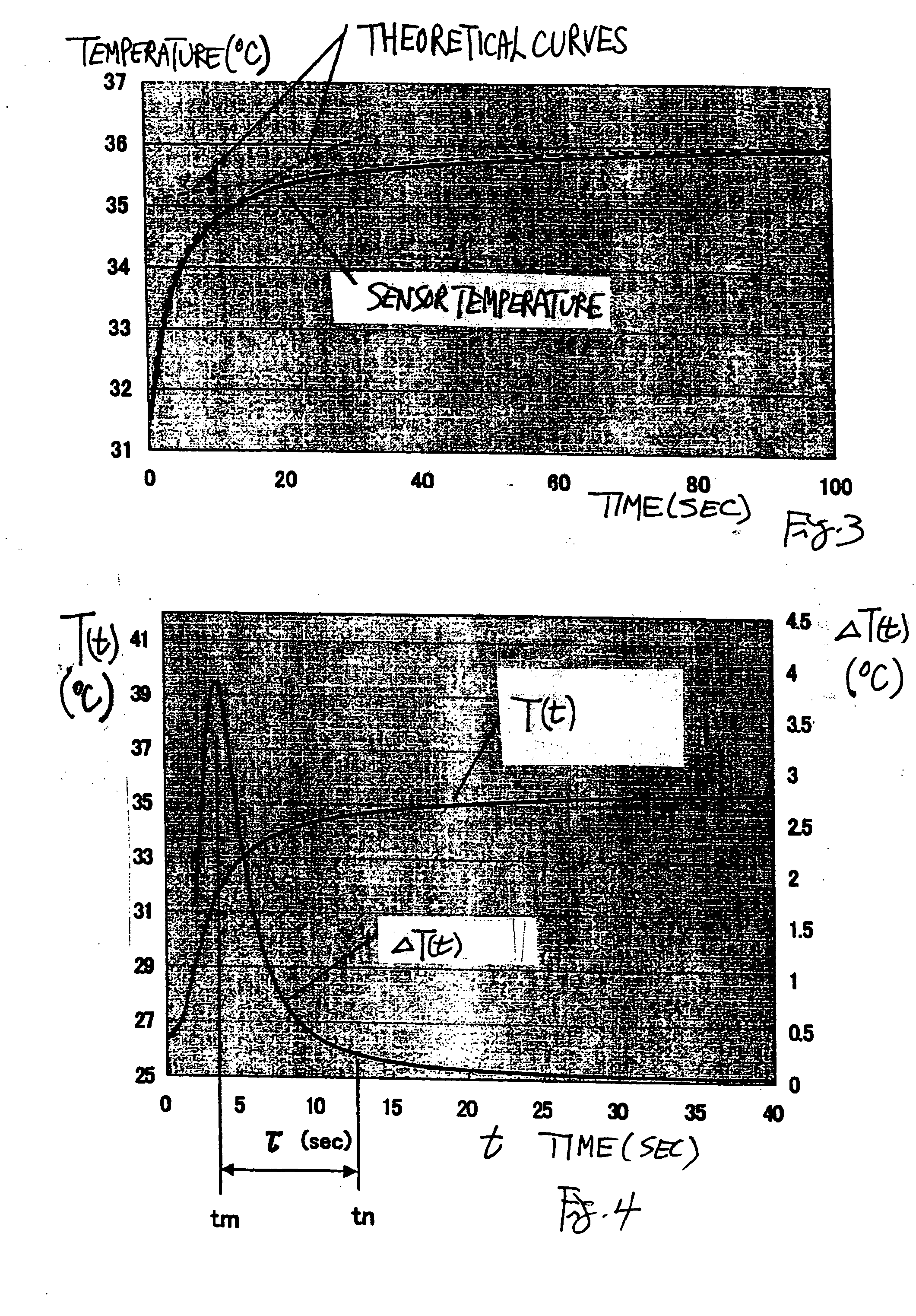
An electronic clinical thermometer according to this invention may be characterized as comprising a temperature measuring device for measuring a live body temperature and a temperature estimating device for estimating an equilibrium body temperature from a first data item related to change in temperature measured by the temperature measuring device during an initial period from the start of a measurement until a specified condition becomes satisfied and a second data item related to change in temperature measured by the temperature measuring device after this initial period. In the above, the specified condition that ends the initial period may be that a peak be detected in the time-rate of change in temperature measured by said temperature measuring device. The initial period may be typically in the range of 3-30 seconds, or about 20 seconds. With a thermometer thus characterized, the equilibrium temperature can be estimated at least in part from the initial temperature change data and a highly accurate measurement of temperature becomes possible within a short measuring time.
With a thermometer embodying the invention, body temperature of a patient can be measured accurately within a short time.

Problems solved by technology

In other words, the earlier portion was not used in the analysis because it is easily influenced by the initial condition of the temperature-measuring part and the skin surface and such conditions are unstable.
With prior art thermometers of this type, the accuracy of estimate was generally poor especially if the time of measurement was short because the effects of the initial conditions were ignored.

Method used


Image

  • Electronic clinical thermoneter
  • Electronic clinical thermoneter
  • Electronic clinical thermoneter

Examples


Embodiment Construction

The invention is described next by way of examples.

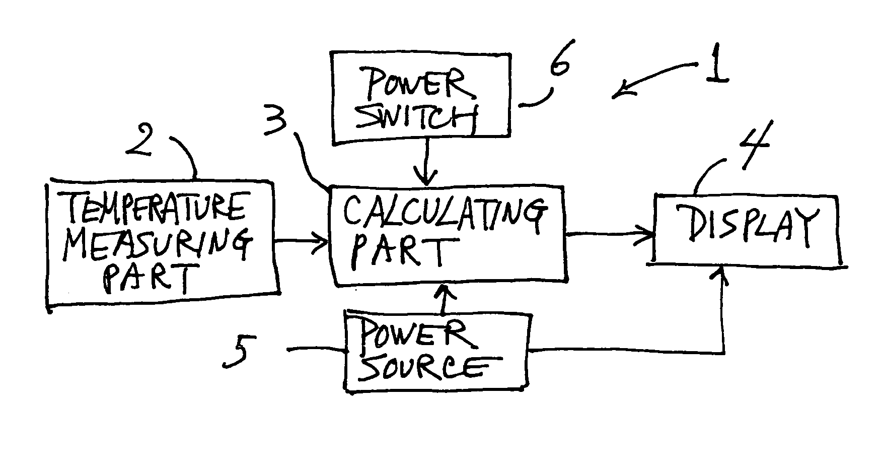
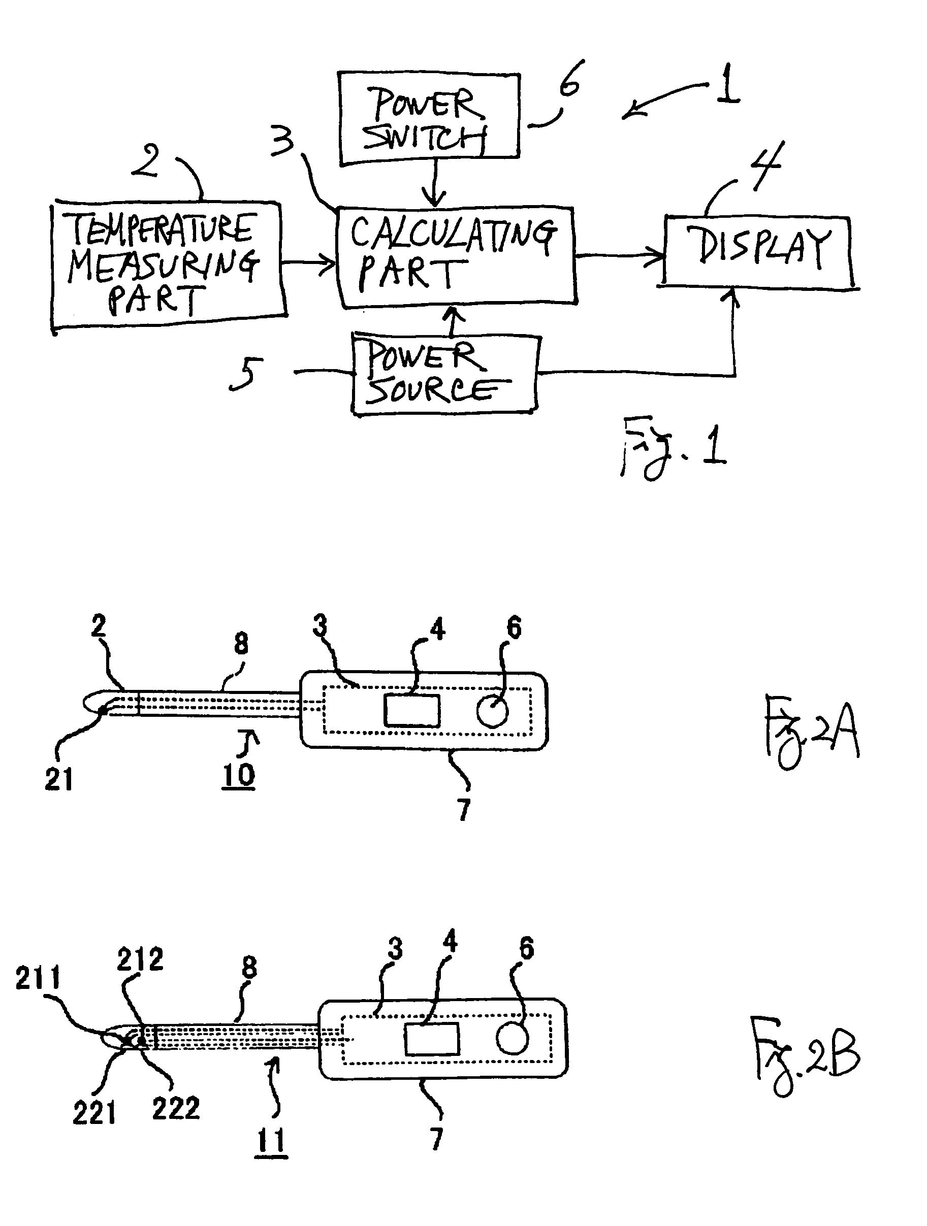
FIG. 1 is a block diagram that shows the basic structure of an electronic clinical thermometer 1 of the type embodying this invention for estimating the body temperature, comprising a temperature measuring part (or “temperature measuring device”) 2, a calculating part (or “temperature estimating device”) 3 for calculating an estimated equilibrium body temperature, a display 4 for displaying the estimated equilibrium body temperature calculated by the calculating part 3, a power source 5 for supplying electric power to the calculating part 3 and the display 4, and a power switch 6 for switching on and off the supply of electric power from the power source 5. The temperature measuring part 2 may comprise a temperature sensor such as a thermistor. The calculating part 3 monitors the signals received from the temperature sensor of the temperature measuring part 2 and estimates the equilibrium temperature at a specified inner body part...


PUM


Abstract

An electronic clinical thermometer has one of two temperature measuring devices each for measuring a live body temperature. A temperature estimating device estimates an equilibrium body temperature from a first data item related to change in temperature measured by the temperature measuring device during an initial period within a specified time such as about 20 seconds from the start of a measurement and a second data item related to change in temperature measured by the temperature measuring device after the initial period. If two temperature measuring devices are used, the first data item may related to the difference between temperatures measured by these two temperature measuring devices and the second data item may related to the time-rate of change in temperature measured by either of the two temperature measuring devices. The first data item may be a value obtained from the linear relationship between the temperature value measured by either of the two temperature measuring devices and the difference between them.

Description

BACKGROUND OF THE INVENTION This invention relates to electronic clinical thermometers of the temperature-estimating type. Electronic clinical thermometers are roughly divided into two categories. Thermometers of one of the categories are adapted to directly display the temperature of its temperature-measuring element inside a temperature-measuring part. With a thermometer of this type, its temperature-measuring part is placed under the arm or inside the mouth where temperature is intended to be measured, and the measured temperature when it stops rising, or the equilibrium temperature, is considered to be the body temperature at the desired body part. It is generally considered to take about 5 minutes to reach an equilibrium temperature if such a thermometer is placed in the mouth and more than 10 minutes if it is inserted under the arm. Some thermometers of this type are adapted to activate a buzzer when the temperature rise becomes smaller than a specified value and to end the ...

Claims


Application Information

Patent Timeline
IPC IPC(8): G01K7/42G01K13/00
CPCG01K13/002G01K7/42G01K13/20
Inventor TOKITA, MUNEOTOMIOKA, SHIGERU
Owner OMRON HEALTHCARE CO LTD
Learn More