Video data conversion device and video data conversion method

a video data and conversion device technology, applied in the field of video data converter and video data conversion method, can solve the problem of not ensuring the optimum conditions in terms of coding performance of the motion vector

Inactive Publication Date: 2005-02-24
MITSUBISHI ELECTRIC CORP
View PDF3 Cites 87 Cited by
  • Summary
  • Abstract
  • Description
  • Claims
  • Application Information

AI Technical Summary

Benefits of technology

Thus, it offers an advantage of being able to covert the motion vectors and the

Problems solved by technology

The problem is a one that estimates a motion vector after the resolution conversion from four original motion vectors at the maximum, and a variety of studies and reports have been made about it up to now.
With the foregoing configuration, the conventional vide

Method used


Image

  • Video data conversion device and video data conversion method
  • Video data conversion device and video data conversion method
  • Video data conversion device and video data conversion method

Examples


embodiment 1

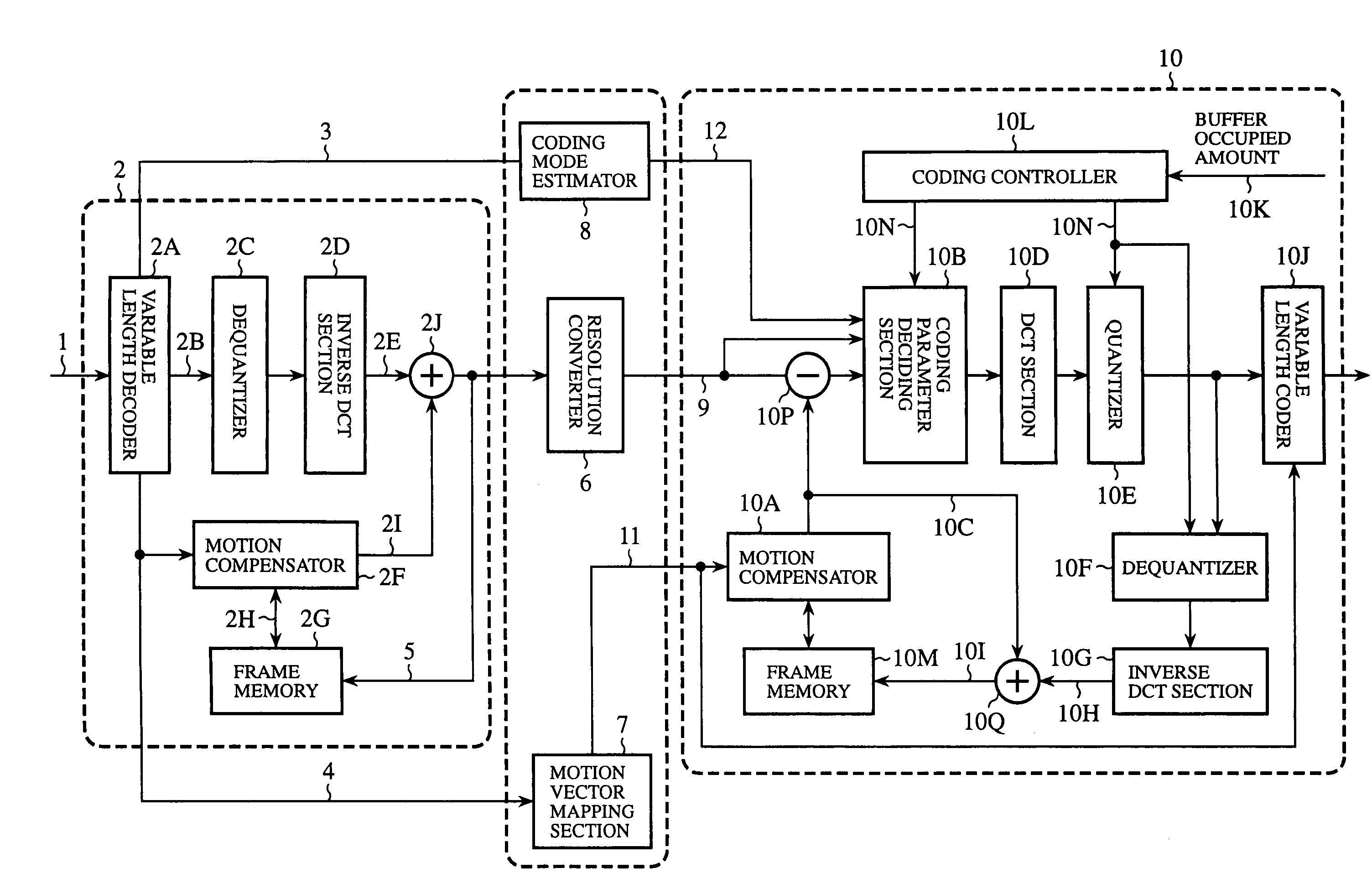
The present embodiment 1 will be described by way of example of a video transcoder that inputs MPEG-2 video data and outputs MPEG-4 video data whose spatial resolution is downsampled-by-two in the vertical and horizontal directions. The following description is made under the assumption that the MPEG-4 is a coding scheme conforming to the MPEG-4 simple profile.

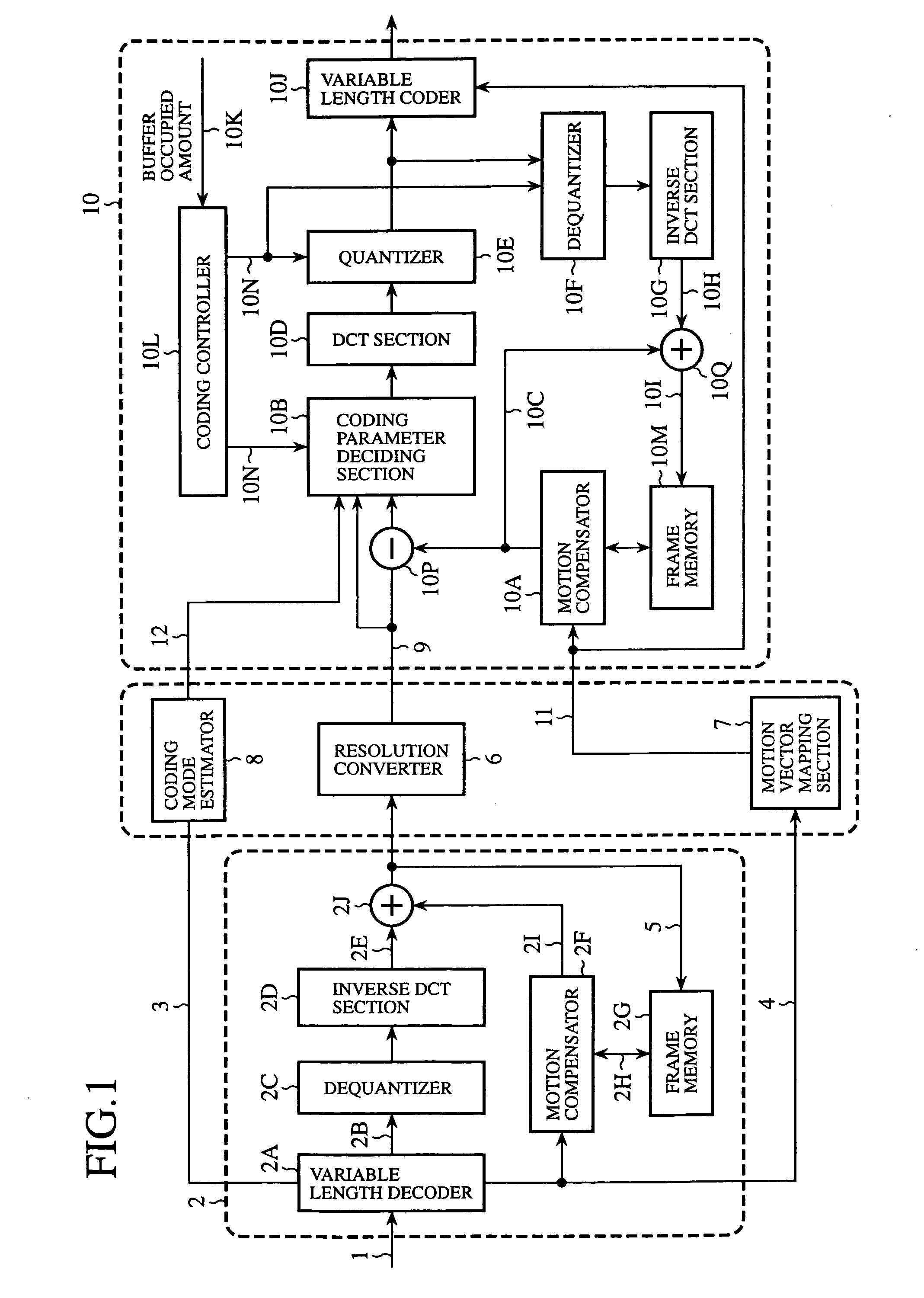
FIG. 1 is a block diagram showing a configuration of a video transcoder (video data converter) of an embodiment 1 in accordance with the present invention. In FIG. 1, an MPEG-2 decoder 2 receives input compression data 1 compressed according to a coding scheme conforming to MPEG-2, and generates a decoded picture 5 from the input compression data 1. A variable length decoder 2A carries out syntax analysis of the input compression data 1 according to the MPEG-2 standard, and generates prediction residual signal coded data 2B, coding mode information 3 and motion vector information 4. A dequantizer 2C dequantizes the predictio...

embodiment 2

In the present embodiment 2, the resolution converter 6 operates not only as the spatial resolution converter, but also as a temporal resolution converter for carrying out the temporal resolution (frame rate) conversion by decimating the P frames to which the effect of the motion prediction is transmitted. The resolution converter 6 can function as both the spatial resolution converter and temporal resolution converter, or as the temporal resolution converter without functioning as the spatial resolution converter.

FIG. 5 is a block diagram showing a configuration of a video transcoder (video data converter) of the embodiment 2 in accordance with the present invention. The configuration of the transcoder of the present embodiment 2 has the same internal configuration as the transcoder of the embodiment 1 as shown in FIG. 1. It differs from the foregoing embodiment 1 in the operation of the resolution converter 6 and motion vector mapping section 7, which will be described in detail...


PUM


Abstract

In an MPEG-2 decoder (2), a variable length decoder (2A) carries out syntax analysis of input compression data (1) according to the MPEG-2 standard, and generates coding mode information (3), motion vector information (4) and prediction residual signal (2B). The prediction residual signal (2B) is transformed to a decoded picture (5) through a dequantizer (2C) and the like, and is supplied to an MPEG-4 encoder (10) via a resolution converter (6). In the MPEG-4 encoder (10), a coding parameter deciding section (10B) decides a motion vector according to a prediction error estimation value for evaluating a prediction efficiency when using a motion vector candidate generated by a motion vector mapping section (7), and according to a value for evaluating a motion vector rate when using the motion vector candidate.

Description

TECHNICAL FIELD The present invention relates to a video data converter and video data converting method for carrying out various conversions of video compression data conforming to video compression-decompression schemes of a variety of international standards. BACKGROUND ART At present, international standard video coding schemes such as MPEG and ITU-T H.26x are utilized in a variety of applications in the fields of broadcasting, communications and packages such as digital broadcasting (satellite, terrestrial, cable), DVDs, video CDs, the Internet and mobile communications. The need is growing for reusing video contents compressed by these coding schemes in a variety of platforms under conditions different in supporting coding schemes, transmission bit rates, spatial resolutions (frame sizes), temporal resolutions (frame rates). With this as a background, intensive research and development of video transcoding technology has been conducted. In particular, the standard video co...

Claims


Application Information

Patent Timeline
IPC IPC(8): H03M7/36H04N19/51H04N19/105H04N19/109H04N19/12H04N19/126H04N19/136H04N19/137H04N19/139H04N19/147H04N19/159H04N19/176H04N19/186H04N19/196H04N19/40H04N19/423H04N19/50H04N19/503H04N19/513H04N19/523H04N19/567H04N19/573H04N19/577H04N19/587H04N19/59H04N19/61H04N19/625H04N19/91H04N19/93
CPCH04N19/139H04N19/159H04N19/147H04N19/172H04N19/51H04N19/513H04N19/59H04N19/107H04N19/132H04N19/16H04N19/19H04N19/587H04N19/40H04N19/61
Inventor SEKIGUCHI, SHUNICHIYAMADA, YOSHIHISAOGAWA, FUMINOBUASAI, KOHTARO
Owner MITSUBISHI ELECTRIC CORP
Why Eureka
Try Eureka