Method and apparatus for manufacturing spark plug

Active Publication Date: 2005-02-24
DENSO CORP
View PDF2 Cites 16 Cited by
  • Summary
  • Abstract
  • Description
  • Claims
  • Application Information

AI Technical Summary

Benefits of technology

[0008] The present invention has been made with due consideration to the foregoing difficulty, and an object of the present invention is to raise accuracy i

Problems solved by technology

However, this lateral movement is limited by the s

Method used


Image

  • Method and apparatus for manufacturing spark plug
  • Method and apparatus for manufacturing spark plug
  • Method and apparatus for manufacturing spark plug

Examples


Example

[0024] In connection with FIGS. 1 to 5, a preferred embodiment according to the present invention will now be described, in which a method and apparatus for manufacturing spark plugs are reduced into practice.

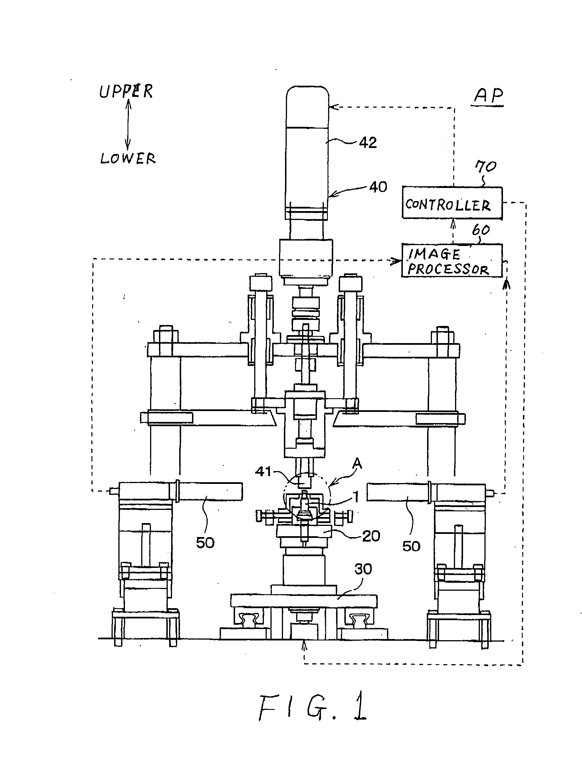
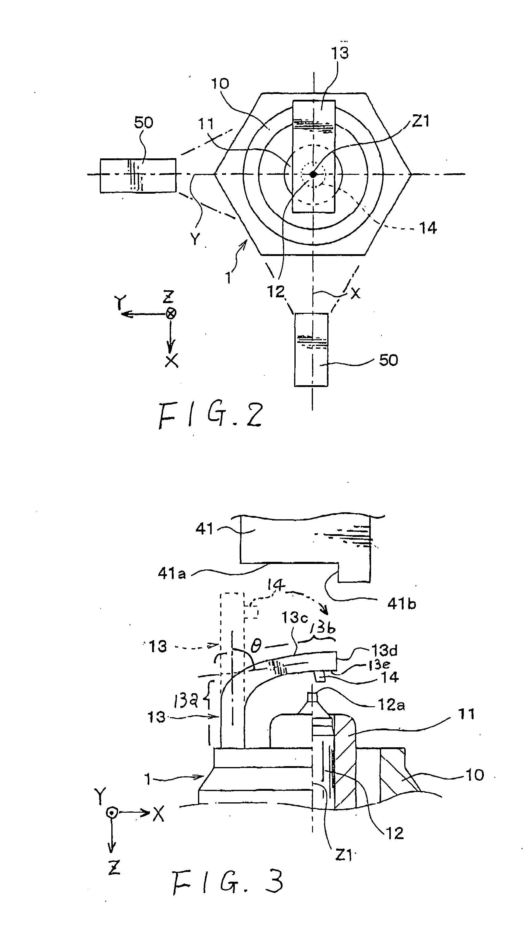
[0025] In the present embodiment, a spark plug is manufactured by a manufacturing apparatus shown in FIG. 1. This manufacturing apparatus is provided with cameras, as will be described later, of which arrangement is pictorially shown in FIG. 2. A spark plug is manufactured through various processes including processes for bending an earth electrode of the spark plug, the bending processes being pictorially shown in FIGS. 3 and 4.

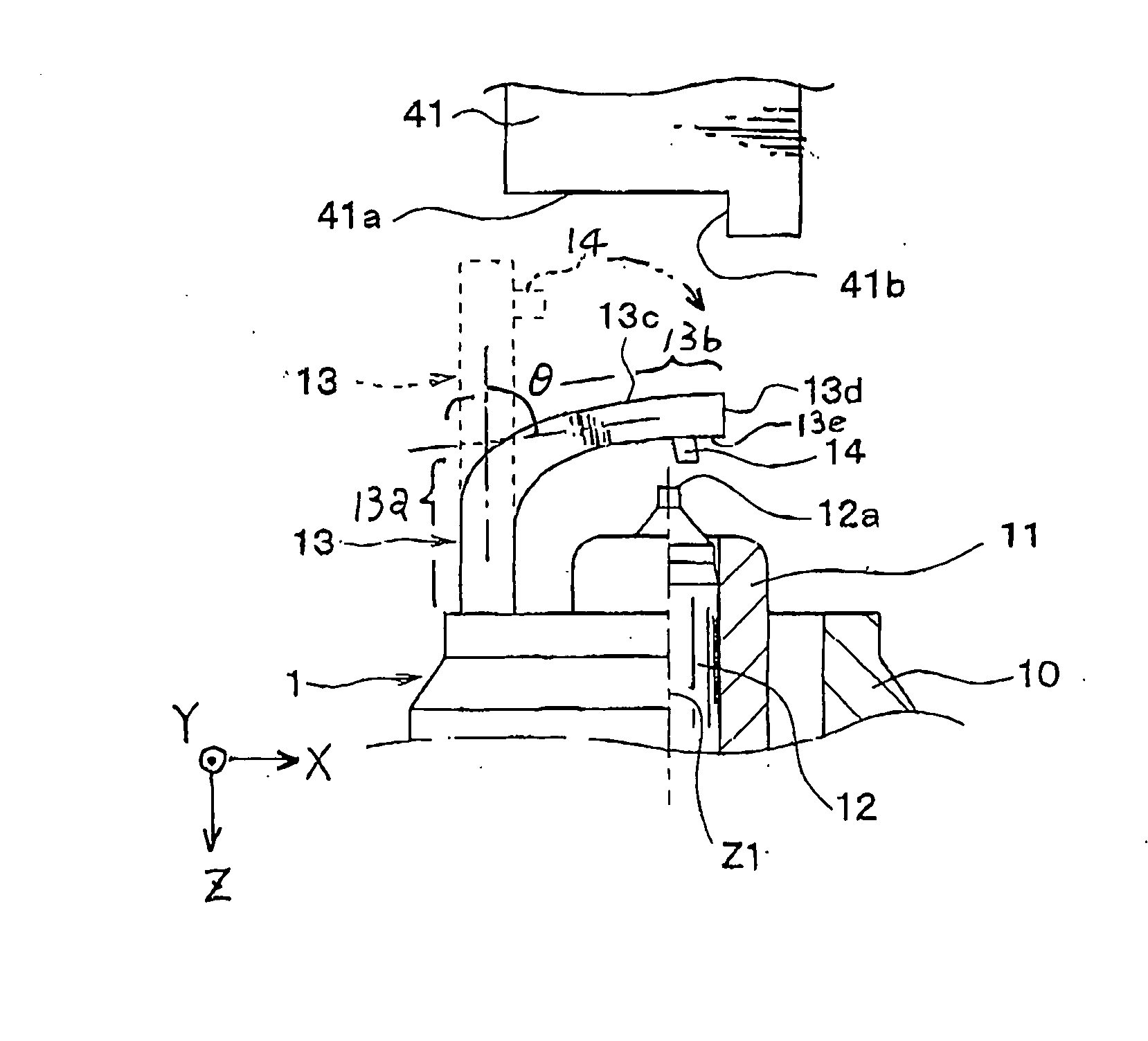
[0026] Prior to the explanation of the manufacturing processes for a spark plug 1, the spark plug 1 will now be explained in terms of its structure with reference to FIGS. 3 and 4.

[0027] As shown in FIGS. 3 and 4, the spark plug 1 has a housing 10, which is made of conductive steel material, is formed into a substantial cylindrical shape. A substanti...


PUM

PropertyMeasurementUnit
Angleaaaaaaaaaa
Lengthaaaaaaaaaa
Distanceaaaaaaaaaa

Abstract

A spark plug is provided after a provisional bending process, during which the earth electrode is provisionally bent at almost 90 degrees. The earth electrode, one of both ends is joined to a housing member, has first and second end-side surfaces located mutually back to back and a tip surface connecting both end-side surfaces. A noble metal chip is mounted on the first end-side surface. A bending punch is set, which has a first pressing surface to be fitted to the second end-side surface located and a second pressing surface to be fitted to a tip surface. The bending punch is first moved so that the second pressing surface comes in contact with the tip surface of the earth electrode, and then moved so that the first pressing surface presses the second end-side surface in the axial direction of the center electrode. Accordingly, a main bending process is performed.

Description

BACKGROUND OF THE INVENTION [0001] 1. Technical Field [0002] The present invention relates to a method of manufacturing spark plugs attached to an internal combustion engine mounted on an automobile. [0003] 2. Related Art [0004] In an internal combustion engine, spark plugs are mounted to start the engine. The conventional spark plug is provided with a pillar-like center electrode held in an insulation manner within a housing member and an earth electrode one end of which is joined to the housing. The earth electrode is bent at its intermediate predetermined portion so as to make its other end (free end) face a tip of the center electrode. On the other end of the earth electrode, there is formed a noble metal chip. Thus ending the earth electrode is made to form a predetermined-size space, called “spark gap,” between the noble metal chip and the tip of the center electrode. [0005] How to manufacture the spark plug is proposed by, for example, Japanese Patent First Publication No. 20...

Claims


Application Information

Patent Timeline
IPC IPC(8): H01T13/20H01T21/02H01T21/06
CPCY10T29/5195H01T21/02
Inventor ODA, SYUSHITAMURA, SHIGEKI
Owner DENSO CORP
Why Eureka
Try Eureka